User’s Manual DAQSTATION CX Operator CX1000/CX2000 IM 04L31Q01-04E 1st Edition
Foreword This manual describes an instruction of CX Operator. To ensure correct use, please read this manual thoroughly before beginning operation. Refer to the manuals supplied with CX1000/CX2000 for the product functions and settings. After you have read this manual, keep it in a safe place where it can be referred to anytime a question arises.
Contents Foreword ..........................................................................................................................................i Note..............................................................................................................................................i Copy Rights ..................................................................................................................................i Trade Mark ...................................................
Chapter 1 Before using CX Operator 1.1 Overview of CX Operator CX Operator allows you to execute recording START/STOP and control loop operations with monitoring measurement/control screen. Operation screens such as CX trend screen, control screen, and program screen can be switched and monitored from remote site. Operations related to trend recording, control operation such as parameters (SP, OUT, operation mode) can be executed from remote site.
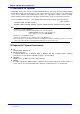
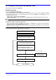
1.3 CX Operator Installation and Operation Flow CX Operator is provided on a CD-ROM. Installation procedure 1. Turn on the computer. Windows starts. 2. Insert the CD-ROM into the CD-ROM drive of the computer. 3. The installation program starts automatically. Follow the instructions on the screen to proceed with the installation. If the installation program does not start automatically when you insert the CDROM into the CD-ROM drive, use the following procedure to start it.
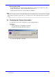
1.4 Registration of CX IP Address After running “Simple control panel”, register CX IP address you wish to connect. 1. Register Open Register window by clicking (1) icon or selecting register from file menu 2. Add a new item Add new CX IP address (2): Enter new CX IP address (3): Delete a current item or move item up/down or change the item order 3. After CX operator registration, click “OK”, the dialog window will be closed and the registration is completed.
1.5 Login CX Login procedure: 1. Open CX Login window by clicking (1) icon or selecting login from file menu. 2. Select CX host name that you have registered in 1.4 chapter. 3. Enter User Name and Password (see the below Note). 4. When CX Login settings are set, click [OK]. To cancel the settings, click [Cancel]. After succeeding the communication, CX control screen will be displayed.
Communication Period Set communication cycle between CX and “CX Operator”: click (2) icon in figure 2 or select “Config” from file menu. Unit for communication cycle is m sec. Communication period can be set from 1000 ms to 60000 ms. Note • When there are large amount of communication data between CX and CX operator, some data cannot be updated within setting communication period. In that case, set longer period in order to update data within communication period. 1.
Chapter 2 CX Operator Operation (Login by an administrator level) 2.1 CX Operator Display After succeeding communication with CX, the connected CX display screen is displayed. (1) Control tool bar Figure 3 CX Operator operation display Control Tool Bar Click View (check “Control tool bar”) and the icons display ON/OFF of control/ trend/digital/bar/ overview/snapshot can be selected.
2.1 CX Operator Display Display Screen Style Display screen style change: Click (3) icon, or select “Style shift” in file menu. Display screen style is changed as follows. (1) Logout (2) Refresh (3) Style shift Figure 4 CX display screen1 Figure 5 CX display screen 2 Refresh CX Data update: Click (2) icon or select Refresh in file menu. When on site CX parameter settings are changed, “Refresh” data. Logout CX operator logout: Click (1) icon, or select “Logout” in file menu.
2.2 Control Operation Display Click the and select the “control group no.” you wish to display, and the CX Operator display will be the selected control display. (1) (2) (3) (4) (5) (6) (7) (8) Figure 6 Control related screen Control screen display (1) : Control functions related to display (2): Followings display types can be selected.
2.2-1 Program control display When the “program” is selected in figure 6 (2), a program selection screen is displayed (figure 7). (1) PT# (2) Run (3) Send Figure 7 Program selection screen (1) (PT#): Program pattern no. can be specified. (2) (RUN): RUN/Reset for the selected pattern no. in (1) is set. (3) (Send): The RUN/Reset for the selected pattern no. in (1) can be executed.
2.2-1 Program control display When some program patterns are running From the menu, - [program], program pattern screen can be switched when some program patterns are running. (1) Program pattern no. display Figure 9 Program operation screen 2 (1) Program pattern no. display: Running program pattern no.s are displayed. Program pattern no. screen switching: Select a program pattern no. you wish.
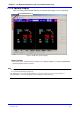
2.3 Trend Display Click an icon, and select a group no. you wish to display. The display screen will be switched to the selected trend display screen (Figure 11). Figure 10 Trend group switching (1) Trend display Figure11 Trend display screen (1): Trend display group selection: Display group no.
2.4 Digital Display Click an icon, and select group no. you wish to display. The display screen will be switched to the digital display screen. (See figure 12) (1) Digital display Figure 12 Digital display screen (1) Digital display screen: Display group no.
2.5 Bar-graph Display Click an icon, and select a display group you wish to display, the display will be switched to the bar graph display. (Figure 13) (1) Bar graph display Figure 13 Bar graph display (1) Bar graph display screen: Display group no.
2.6 Overview Display Click the icon, and the display will be switched to overview display screen. (Figure 14) (1) Overview display (2) Snap shot Figure 14 Overview screen (1): Overview display screen selection 2.7 Screen Snapshot Click the icon, and the CX screen image that is displayed in CX operator can be saved in a file. The screen image is saved as a png file in your specifying PC file. (2): The display screen image is saved.
2.8 The Other Function Key Operations Memory start/stop, Math start/stop, Math reset, alarm ACK, save data in media, and message write can be executed by the keys in the display below. (8) (7) (1) (2) (3) (4) (5) (6) Figure 15 Operation function keys (1) (2) (3) (4) (5) (Start/Stop memory) Memory start/stop can be executed. (Start/Stop math) Math start/stop can be executed. (Math Reset) Math data can be reset.
2.8 The Other Function Key operations Message write Message write is executed with soft key displayed in right side below. During memory start, the message write function key is available. Click the key and (1) window will be open. Select a message you wish to write. (1) (1) Figure 16 Message function key (1) (Message): Message 1-8 you wish to write can be selected. For model with /S33 or /S35: Message 1-8 corresponds to message 1-8 of 1 group in CX.
Chapter 3 CX Operator Operation (Login by a user level) 3.1 CX Operator Display After login by a user level, the digital values for each display group are displayed. Operation Display data group for control data or measurement data can be selected. (1) Control: Control data can be selected. (2) Measurement: Measurement data can be selected. (3) Group: Display group for each control/measurement data can be selected.
Appendix General Specification: z Communication Ethernet(10baseT) TCP/IP protocol z Display type Control Display: Control group (embedded loops, external loops, DIO, measurement channels), MODE, SP, PV, OUT, Internal SW status, DI/DO status, Program pattern number Measurement display: Tag name, type (embedded loops, external loops, measurement channels, Math channels), PV z Available Setting Items Communication period: Communication period (1000 to 60000ms) Control: Mode (MAN/AUTO/CAS), LOC/REM (or PRG) sw