Operation Guide Model CX2000/CX2010/CX2020/CX2200/CX2210/CX2200/ CX2410/CX2420/CX2610/CX2620 DAQSTATION CX2000 IM 04L31A01-02E 6th Edition Yokogawa Electric Corporation
Contents Introduction to Control Functions ................................................................................................................................... 4 Control Types ........................................................................................................................................................... 4 PID Control Function ..............................................................................................................................................
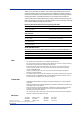
Thank you for purchasing the CX2000. This operation guide briefly explains the main operations related to the loop control function of the CX2000. For information about all the functions excluding the communication functions, installation and wiring procedures, operating procedures, and handling precautions of the CX2000, see the electronic manual CX2000 User’s Manual (IM 04L31A01-01E) provided on the accompanying CDROM.
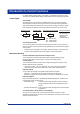
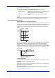
Introduction to Control Functions For further details on each function, see chapter 1, “Explanation of Functions” in the CX2000 User’s Manual (IM 04L31A01-01E) provided on the accompanying CD-ROM. Control Types Control Mode The following four control modes are available (three types of control plus analog retransmission) and can be set for each control loop. The mode can be specified for each control output terminal block (two loops per block, see page 7).
Introduction to Control Functions PID Parameter Selection Method You can select the method for switching PID parameters from the following: • Target setpoint selection: By specifying the SP number. • Zone PID selection: By dividing the measurement span in to multiple zones and determining in which zone the PV resides. • Segment PID selection: Using the program pattern segment when in program control.
Introduction to Control Functions Preset Output This function sets the control output to the preset value when the operation is stopped. SP Ramp-Down-Rate/SP Ramp-Up-Rate This function is used to decrease or increase the setpoint at a constant rate of change (as opposed to a rapid change) when the SP is changed. Target Setpoint Limit This function is used to limit the range of values that the SP can change.
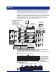
Wiring Input/Output terminals are arranged on the rear panel of the CX2000 as shown in the figure below. The figure shows the case when option terminals are specified on the model with 6 internal control loops and 20 measurement channels (CX2620). For the wiring procedure of the control/measurement input/output, see chapter 2, “Installation and Wiring” in the CX2000 User’s Manual (IM 04L31A01-01E) or the CX2000 Installation and Connection Guide (IM 04L31A01-71E).
Overview of Operations Key Operation For details on the key operation, see chapter 3, “Names of Parts, Display Modes, and Common Operations” in the CX2000 User’s Manual (IM 04L31A01-01E).
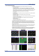
Overview of Operations Control Operation Display In operation mode, the following control operation displays can be selected. • Control group display This display is used to monitor the control status of multiple loops simultaneously including external loops. You can select from three display styles as shown in the display example in the figure below.
Overview of Operations List of Control Setup Items Basic Control Setup Items in Basic Setting Mode #1 Control action, Input setting PID number, control period, zone PID, restart mode, restart mode (program) (only on models with the program control option), initial PID, 6/4 loop select (only on models with six loops), auto tuning, control mode, method (only during loop control with PV switching), program control ON/OFF (only on models with the program control option), PID control mode, burnout, and RJC.
Examples of Control Setup Operation Control Setup Example 1: Single Loop Control Object of Control and Description CX2000 Alarm output DIGITAL OUT13 PV TC LOOP1 PV1 High limit temperature alarm DIGITAL OUT23 Electric furnace Low limit temperature alarm 1 2 3 4 5 6 11 16 21 26 7 12 17 22 27 8 13 18 23 28 9 14 19 24 29 10 15 20 25 30 DISP /ENTER 1 Loop 1 PV input terminal of the control input terminal block LOOP1 2 Loop 1 voltage pulse output terminal Voltage-pulse of the c
Examples of Control Setup Operation 2. Press the #1 soft key (Control action, Input setting). 3. Press the arrow keys to move the cursor (blue) to the setup item box, press the soft key of each value according to the following figure, and then press the DISP/ENTER key. Select Temp (Set initial PID to P = 5%, I = 240 s, and D = 60 s) Select 1 Select Single (single loop) 4. Press the ESC key to return to the basic control setting menu. 5. Press the #3 soft key (Output processing). 6.
Examples of Control Setup Operation Setting the Control Input Range in Setting Mode 1. From the operation display, click the MENU key to display the control setting menu shown below. 2. Press the #1 soft key (Control input range). 3. Press the arrow keys to move the cursor (blue) to the setup item box, press the soft key of each value, and press the DISP/ENTER key.
Examples of Control Setup Operation Setting Control Alarms in Setting Mode 1. From the operation display, click the MENU key to display the control setting menu. 2. Press the #2 soft key (Control alarm). 3. Press the arrow keys to move the cursor (blue) to the setup item box, press the soft key of each value according to the following figure. The numeric value of the alarm is entered using the pop-up window that appears by pressing the Input soft key.
Examples of Control Setup Operation Control Setup Example 2: Cascade Control Object of Control and Description Alarm output DIGITAL OUT14 CX2000 High limit temperature alarm Primary PV input DIGITAL OUT24 LOOP1 PV1 Low limit temperature alarm DIGITAL OUT34 1 2 3 Pt100 Tank 4 5 6 11 16 21 26 7 12 17 22 27 8 13 18 23 28 9 14 19 24 29 10 15 20 25 30 High limit steam pressure alarm DISP /ENTER LOOP2 PV2 Secondary PV input LOOP2 mA3 4 to 20 mADC current output Pressure tran
Examples of Control Setup Operation Select Tem or Press+Flow Select 1 (No need to set loop 2) Select Cascade 4. Press the ESC key to return to the basic control setting menu. 5. Press the #3 soft key (Output processing). 6. Press the 2 soft key. There are no control output settings on loop 1 (primary loop of cascade control). 7. Press the arrow keys to move the cursor (blue) to the setup item box, press the soft key of each value according to the following figure, and press the DISP/ENTER key.
Examples of Control Setup Operation 9. Press the End soft key. A confirmation window shown below opens. 10.Press the DISP/ENTER key to confirm the settings. Setting the Control Input Range in Setting Mode 1. From the operation display, click the MENU key to display the control setting menu shown below. 2. Press the #1 soft key (Control input range). 3. Press the arrow keys to move the cursor (blue) to the setup item box, press the soft key of each value according to the following figure.
Examples of Control Setup Operation 6. Set the input range of the secondary loop of cascade control in a similar fashion as described in steps 3 to 5 and according to the figure below. If you do not carry out steps 4 and 5 and change Loop number, the settings are not saved. Setting the Input Range on the Secondary Loop of Cascade Control Select 2 Select 1-5V Set to 0.00 Set to 1.00 Set to MPa Setting Control Alarms in Setting Mode 1.
Examples of Control Setup Operation Setting Alarms on the Secondary Loop of Cascade Control Select PV-High Select On Select On Select DO003 Select 2 Select 1 Set to 0.90 Setting PID Parameters in Setting Mode 1. From the operation display, click the MENU key to display the control setting menu. 2. Press the #4 soft key (PID parameters). 3. Press the arrow keys to move the cursor (blue) to the setup item box, press the soft key of each value according to the following figure.
Examples of Control Setup Operation Setting PID Parameters on the Secondary Loop of Cascade Control Select 2 Select 1 Select Reverse Set to P=120.
Examples of Control Setup Operation 2. Press the #1 soft key (Control action, Input setting). 3. Press the arrow keys to move the cursor (blue) to the setup item box, press the soft key of each value according to the following figure, and press the DISP/ENTER key. Select Press+Flow Select 1 Select PVSwitching Select Signal 4. Press the ESC key to return to the basic control setting menu. 5. Press the #3 soft key (Output processing). 6.
Examples of Control Setup Operation 3. Press the arrow keys to move the cursor (blue) to the Input type box, press the PV1 soft key, and set other parameters as shown in the figure below. Check that 1 is selected Select PV1 Select 1-5V Set to 0.00 Set to 300.00 Set to kg/h 4. Press the DISP/ENTER key. A confirmation window opens. 5. Press the DISP/ENTER key to confirm the settings. 6.
Examples of Control Setup Operation Setting PID Parameters in Setting Mode 1. From the operation display, click the MENU key to display the control setting menu. 2. Press the #4 soft key (PID parameters). 3. Press the arrow keys to move the cursor (blue) to the setup item box, press the soft key of each value according to the following figure. The numerical values such as the SP are entered using the pop-up window that appears by pressing the Input soft key. Select 1 Select 1 Set to 100.
Examples of Control Setup Operation 2. Press the #1 soft key (Control action, Input setting). 3. Press the arrow keys to move the cursor (blue) to the setup item box, press the soft key of each value according to the following figure, and press the DISP/ENTER key. Select Temp Select 1 Select Single 4. Press the ESC key to return to the basic control setting menu. 5. Press the #3 soft key (Output processing). 6.
Examples of Control Setup Operation 2. Press the #1 soft key (Control input range). 3. Press the arrow keys to move the cursor (blue) to the setup item box, press the soft key of each value according to the following figure. The numeric values of the lower/upper limit of range are entered using the pop-up window that appears by pressing the Input soft key. Select 1 Select PV1 Select TC Select K Set to 0.0 Set to 1200.0 4. Press the DISP/ENTER key. A confirmation window shown below opens. 5.
Examples of Control Setup Operation Setting the Display Items on the Control Group Display (Control Group Setting) Below are the procedures for displaying loops 1 to 5 and measurement channel (input channel for measurement) 1 on the control group display (group name: CONTROL GROUP 1) of group number 1. 1. From the operation display, click the MENU key to display the control setting menu shown below. 2. Press the #5 soft key to show the Control group setting display. 3.
Displaying the Trend of PV, SP, and OUT Values Below are the procedures for displaying the trends of PV, SP, and OUT of loop 1 on the trend display of group number 1 (group name: GROUP 1). 1. From the operation display, open the Group set, Trip line setting display according to the following procedure. Press the MENU key (to switch to Setting mode (Control)) and then the MENU key (switch to Set mode). Press the #4 soft key (to select Display) and then the #1 soft key (to select Group set, Trip line).
Displaying the Trend of PV, SP, and OUT Values Note You can select up to 10 channels from measurement channels (CH1 to CH20), computation channels (CH31 to CH60), internal control channels (CH101 to CH118), and external control channels (CH201 to CH248) using Channel setting. • Assignment of internal control channels (channels of internal loops) The data of 6 loops is assigned to channel numbers as follows: Loop 1 PV: 101, Loop 1 SP: 102, Loop 1 OUT: 103 ...
Switching the Operation Mode For details on the procedure for switching the operation mode, see chapter 6, “Operations during Control Operation” in the CX2000 User’s Manual (IM 04L31A01-01E). The following is a procedural example on the control group display. Run/Stop Operation For cascade control, the following operations can be performed only when the secondary loop is selected. 1. Use the arrow keys to move the cursor to the desired control loop. Cursor ( ) 2. Press the RUN/STP soft key.
Switching the Operation Mode Changing the Target Setpoint 1. Use the arrow keys to move the cursor to the desired control loop. 2. Press the SP soft key. The SP modification pop-up window appears. The window shows the current target setpoint. Window for changing the target setpoint 3. Change the target setpoint using the up and down arrow keys. 4. Press the DISP/ENTER key to confirm the changes.
Switching the Operation Mode Switching between Remote and Local Modes The soft key menu does not show REM/LOC, if Control > Contact input-registration/ AUX(Alarm mode... > Remote setting is set to Off. Remote input cannot be used for the target setpoint when the secondary loop of cascade control is selected or during program control. Thus, there is no remote/local switching in these cases. 1. Use the arrow keys to move the cursor to the desired control loop. 2. Press the REM/LOC soft key.
Switching the Operation Mode Changing the Analog Retransmission Output MAN must be set for the MODE using the procedure above. 1. Use the arrow keys to move the cursor to the desired control loop 2. Press the OUT soft key. The Output Value Setting window appears. 3. Change the output value using the up and down arrow keys. The currently set control output value is displayed in the window.
Tuning Operation For details on the procedure of switching the operation mode, see chapter 6, “Operations during Control Operation” in the CX2000 User’s Manual (IM 04L31A01-01E). Displaying the Tuning Display Press the TUNING soft key on the control group display. → Auto Tuning To execute auto tuning, Basic setting mode > #10 Control > #1 Control action, Input setting > Auto tuning must be turned On before carrying out the following procedure. 1. Press the AUTO TUN soft key on the tuning display.
Tuning Operation Manual Tuning 1. Press the arrow keys on the tuning display. A cursor appears in the control parameter display section. 2. Select the control parameter you wish to change using the arrow keys. 3. Press the DISP/ENTER key. The parameter modification pop-up window appears. Cursor ( ) Control parameter display section Window for changing parameters 4. Change the value using the up and down arrow keys. 5. Press the DISP/ENTER key to confirm the changes.
Program Control Function (/PG1 and /PG2 Options) Program Control Function Introduction SP Program control function is used to ramp-up or ramp-down the SP according to a program pattern. The number of program patterns that you can create with the CX2000 is as follows: • /PG1 option: 4 • /PG2 option: 30 Up to 99 segments can be specified in a single pattern. Time /PG1: 4 patterns /PG2: 30 patterns Segment Operation Mode during Program Control The following 4 types of operation modes are available.
Program Control Function (/PG1 and /PG2 Options) Program Selection Display Example Program pattern name Preset pattern waveform * The selected segment is the segment displayed at the left end. Select the segment using the left and right arrow keys.
Program Control Function (/PG1 and /PG2 Options) Resetting Program Control Resets the program control and stops. 1. Press the RUN/RST soft key. A pop-up window for starting and resetting program control appears. Window for starting and resetting program control 2. Select [RESET] using the up and down arrow keys. 3. Press the DISP/ENTER key.
Program Control Function (/PG1 and /PG2 Options) Executing Several Program Patterns You can execute multiple program patterns whose loop numbers do not overlap. Switching Pattern Numbers 1. Press the PT NO. soft key in the program selection screen. The pattern number switching pop-up window appears. The currently set pattern numbers are displayed in the window. 2. Select a pattern number using the up and down arrow keys. 3. Press DISP/ENTER key to confirm the changed settings.
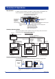
Program Control Function (/PG1 and /PG2 Options) Program Control Related Setup Operations Follow the flow chart below. For further details on each function, see section 1.11, “Program Control Related Settings” in the CX2000 User’s Manual (IM 04L31A01-01E) provided on the accompanying CD-ROM.
Program Control Function (/PG1 and /PG2 Options) Pattern Initial Setting Enter the program pattern number. /PG1: 1 to 4, /PG2: 1 to 30 Enter the number of segments to be used. 1 to 99 Select the time or ramp-rate (see below). Enter the pattern name (up to 16 characters). Specify the position of the segment to be deleted or added. Segment setting method: Time Method for creating the segment using the target SP and the segment time.
Program Control Function (/PG1 and /PG2 Options) Pattern Start Setting Enter the SP of the pattern start point. Select the operation when starting the program control (see below). Select the operation start condition (Start code) from the following. Start code: StartTargetSP Starting SP Start Program starts from the starting target SP.
Program Control Function (/PG1 and /PG2 Options) Program Pattern Setting • When the segment setting method is set to [Time] Select the segment number. Select ramp or soak. p Ram Soak Enter the target SP of the segment. Enter the segment time. Select the PID number to be used (Not displayed when zone PID is selected). Select the operation when ending the segment. • [Continue]: Advance to the next segment. • [Hold]: Hold the program progress. • [Local]: End by setting the loop to local mode.
Program Control Function (/PG1 and /PG2 Options) • When the event kind is set to [PVEvent] Select the segment number to which the event is to be assigned. Select [PVEvent] (see below). Select the loop to which the event is to be assigned. Enter a value when the PV event is to be detected using engineering unit. Select the type of PVEvent (see below). This function outputs preset alarms such as PV alarms, SP alarms, and output alarms during program operation.
List of Parameters Below is a list of parameters for the model with the various function options. However, settings related to the program control function option are not given.
List of Parameters #4 Key login Parameter Selectable Range or Selections Initial Value Key login > Use/Not Key login > Auto logout Key login > UserID Use/Not Key login > Number Key login > On/Off Key login > User name Key login > User ID Key login > Password Key login > setup Use/Not On/Off Use/Not 1, 2, 3, 4, 5, 6, or 7 On/Off Up to 16 alphanumeric characters Up to 4 alphanumeric characters Up to 6 alphanumeric characters On or Off Not Off Not 1 On user1 1 – On Parameter Selectable Range or Selecti
List of Parameters #7 Communication <#1 Ethernet, Serial> Parameter Selectable Range or Selections Ethernet > IP-address – Ethernet > Subnet mask – Ethernet > Default gateway – Ethernet > DNS On/Off On/Off Ethernet > Server search order > Primary – Ethernet > Server search order > Secondary – Ethernet > Host name Up to 64 alphanumeric characters Ethernet > Domain name Up to 64 alphanumeric characters Ethernet > Domain suffix search order > Primary Up to 64 alphanumeric characters Ethernet > Domain suffix
List of Parameters <#5 AUX> Parameter Selectable Range or Selections Initial Value Recovery Status for Comm.
List of Parameters <#6 Report E-Mail Settings> Parameter Selectable Range or Selections Initial Value Report E-Mail settings > Recipient1 Report E-Mail settings > Recipient2 Report E-Mail settings > Include source URL Report E-Mail settings > Subject Report E-Mail settings > Header1 Report E-Mail settings > Header2 On/Off On/Off On/Off Up to 32 alphanumeric characters Up to 64 alphanumeric characters Up to 64 alphanumeric characters Off Off Off (CX) Report_data – – Parameter Selectable Range or Sele
List of Parameters Parameter Selectable Range or Selections Initial Value AUX > Loop number AUX > Remote setting AUX > Alarm mode AUX > SP No.
List of Parameters Parameter Value or Selections Initial Value Control mode SingleLoopControl, CascadePrimaryLoop, CascadeSecondaryLoop, CascadeControl, ControlBackup, PVSwitching, PVAutoSelector, PVHoldFunction, DualLoopControl, Temperature-Humidity, Cascade-2Uni, PVSwitching-2Uni, or PVAutoSelector-2Uni Relay, Voltage-pulse, Current-output, or On/Off-control Off, PH-H-E (PV high-limit alarm (energize)), PV-L-E (PV low-limit alarm (energize)), Dev-H-E (Deviation high-limit alarm (energize)), Dev-L-E (D
List of Parameters Parameter #3 Tuning setting Tuning setting > Loop number Tuning setting > 01 to 21 Tuning setting > Item ID Tuning setting > Item name Tuning setting > Register address Tuning setting > Decimal point Tuning setting > Range lower Tuning setting > Range upper Value or Selections Initial Value Ext1 to Ext16 On/Off SP, A1, A2, A3, A4, P, I, D, OH, OL, MR, H, DR, DB, PO, or ETC Up to 6 alphanumeric characters 30001 to 39999, 300001 to 365535, 40001 to 49999, 400001 to 465535 0 to 4 –30000 t
List of Parameters #3 Operation-related parameter/zone PID Parameter Selectable Range or Selections Operation related/zone PID > Loop number Operation related/zone PID > Suppressing function Operation related/zone PID > Ramp-rate time unit Operation related/zone PID > SP ramp-down-rate 1 to 6 Off or Overshoot Hour, Minute, or Second On/Off Selectable range when On: 1digit to EUS (100.
List of Parameters #7 Program control related (only when program control is ON) <#1 Program parameter setting> Parameter Selectable Range or Selections Initial Value #1 Pattern initial setting Program initial setting > Pattern number Program initial setting > Segments Program initial setting > Segment setting method Program initial setting > Pattern name Program initial setting > Action loop > Loop 1 to 6 1 to 4 (/PG1), 1 to 30 (/PG2) 0 to 99 Time, Ramp Up to 16 alphanumeric characters On/Off 1 0 Time
List of Parameters <#3 AUX (Auto message, Display position)> Parameter Selectable Range or Selections Initial Value AUX (Auto message, Display position) > Auto message for program Run/Reset On/Off AUX (Auto message, Display position) > Program display position > Position > Loop 1 to 6 AUX (Auto message, Display positin) > Auto change to program run display On, Off On 1 to 6 Loop 1 to 6: 1 to 6 On, Off Off Parameter Selectable Range or Selections Initial Value AUX (Event group) > Pattern number
List of Parameters <#4 DI/DO label setting> Parameter Selectable Range or Selections Initial Value DI/DO label setting > Module CTRL1-DI, CTRL2-DI, CTRL3-DI, EXT1-RI, CTRL1-DO, CTRL2-DO, CTRL3-DO, EXT1-RO Up to 16 alphanumeric characters Up to 16 alphanumeric characters Up to 16 alphanumeric characters Up to 16 alphanumeric characters Up to 16 alphanumeric characters Up to 16 alphanumeric characters Up to 16 alphanumeric characters Up to 16 alphanumeric characters CTRL1-DI DI/DO label setting > DI001
List of Parameters Set mode #1 Range, Alarm Parameter Selectable Range or Selections Initial Value First-CH Last-CH Range > Mode Range > Range 01 to 20 01 to 20 Volt, TC, RTD, Scale, Delta, DI, Sqrt, or Skip 20 mV, 60 mV, 200 mV, 2 V, 6 V, 20 V, 50 V, R, S, B, K, E, J, T, N, W, L, U, PLATI, PR, Wre, PT, JPT, Level, or Cont – – On/Off H: High limit, L: Low limit, R: Rate-of-change, T: Delay high, t: Delay low – On/Off I01 to I06, DO001 to DO006, DO101 to DO106, DO201 to DO206, RO001 to RO012, or SW001 t
List of Parameters <#2 Color> Parameter Selectable Range or Selections Initial Value Color > CH1, CH11 Red, green, blue, blue violet, brown, orange, yellow-green, light blue, violet, gray, lime, cyan, dark blue, yellow, light gray, or purple Same as above Same as above Same as above Same as above Same as above Same as above Same as above Same as above Same as above Red Color > CH2, CH12 Color > CH3, CH13 Color > CH4, CH14 Color > CH5, CH15 Color > CH6, CH16 Color > CH7, CH17 Color > CH8, CH18 Color >
List of Parameters <#6 Control (Zone, Graph (, Partial))> Parameter Selectable Range or Selections Initial Value First-CH Last-CH Zone Lower Zone Upper Division Bar graph Scale position Partial Expand Boundary 101 to 118 or 201 to 248 101 to 118 or 201 to 248 0% to 95% 5% to 100% 4, 5, 6, 7, 8, 9, 10, 11, 12, or C10 Normal or Center Off or 1 to 10 On/Off 1% to 99% Minimum span value + 1 digit to maximum span value – 1 digit or minimum scale value + 1 digit to maximum scale value – 1 digit (when the cha
List of Parameters #6 Time Parameter Selectable Range or Selections Initial Value Time set > YY/MM/DD HH/MM/SS – – #7 Math set1 (expression, alarm, constant) Parameter Selectable Range or Selections Initial Value First-CH Last-CH Math range > Math On/Off Math range > Calculation expression Math range > Span Lower 31 to 60 31 to 60 On/Off 40 characters or less.