
Instruction Manual


2-29
IM04L41B01-65EN
1
2
3
4
Index
Viewing and Creating Setup Data
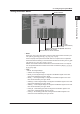
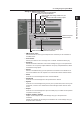
Setting the Modbus Master
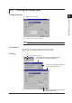
Set the command.
Data type
Select whether or not use command.
Register No. (slave device)
Address (slave device)
Communication input data (DX100P: C01 to C12,
DX200P: C01 to C30)
• Basic
Read cycle: The cycle at which data is read from other devices. Select the read cycle
from [125 ms], [250 ms], [500 ms], [1 s], [5 s], [2 s], or [10 s]
Timeout:SpecifyatimeperiodthattheDXPwaitsforaresponsefromthespecied
slave device after transmitting a command. Select the timeout time from [125 ms], [250
ms], [500 ms], [1 s], [5 s], [2 s], [10 s], or [1 min].
Retrials: The number of times to retransmit the command when there is no response
fromthespeciedslavedevice.Selectthenumberofretrialsfrom[Off](0),[1],[2],[3],
[4], [5], [10] or [20].
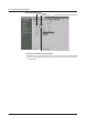
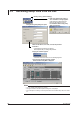
• Type
• INT16:16-bitsignedinteger
• UINT16:16-bitunsignedinteger
• INT32_B:“32-bitsignedinteger”isassignedtotheModbusregisterintheorder
upper 16 bits followed by the lower 16 bits.
• INT32_L:“32-bitsignedinteger”isassignedtotheModbusregisterintheorder
lower 16 bits followed by the upper 16 bits.
• UINT32_B:“32-bitunsignedinteger”isassignedtotheModbusregisterintheorder
upper 16 bits followed by the lower 16 bits.
• UINT32_L:“32-bitunsignedinteger”isassignedtotheModbusregisterintheorder
lower 16 bits followed by the upper 16 bits.
• FLOAT_B:“32-bitoating-pointdata”isassignedtotheModbusregisterinthe
order upper 16 bits followed by the lower 16 bits.
• FLOAT_L:“32-bitoating-pointdata”isassignedtotheModbusregisterinthe
order lower 16 bits followed by the upper 16 bits.
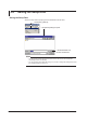
2.6 Configuring the System Mode