User’s Manual DXA120 DAQSTANDARD DX-P Hardware Configurator IM 04L41B01-65EN 4th Edition
User Registration Thank you for purchasing YOKOGAWA products. We invite you to register your products in order to receive the most up to date product information. To register, visit the following URL. http://www.yokogawa.
Thank you for purchasing the DAQSTANDARD (model name: DXA120). This manual explains how to use the software. Please read this manual carefully before operating the software to ensure its correct use. Notes • This software cannot connect to a DX100P/DX200P whose style number is S4 or earlier. • The contents of this manual are subject to change without prior notice. • Every effort has been made in the preparation of this manual to ensure accuracy.
Terms and Conditions of the Software License NOTICE - PLEASE READ CAREFULLY BEFORE USE Thank you very much for purchasing this medium containing a software program and related documentation provided by Yokogawa Electric Corporation (hereinafter called “Yokogawa”), and the program contained, embedded, inserted or used in the medium (hereinafter called the “Yokogawa Software Program”).
Terms and Conditions of the Software License 4.3 When Yokogawa decides in its own judgement that it is necessary, Yokogawa may from time to time provide the Licensee with Release Upgrades specified by Yokogawa (hereinafter called “Release Upgrades”). 4.4 Notwithstanding the preceding Paragraph 4.3, in no event shall Yokogawa provide Updates where the Licensee or any third party conducted renovation or improvement of the Licensed Software. 4.
How to Use This Manual Structure of the Manual This manual consists of the following five chapters and index. Chapter 1 2 3 4 Index Title Before using the DAQSTANDARD Viewing and Creating Setup Data Receiving and Sending Setup Data Troubleshooting Content Explains the PC system environment required for use of the DAQSTANDARD. Also explains how to install it. Explains how to view DX100P/DX200P setup data and how to create new setup data.
Contents 1 Terms and Conditions of the Software License................................................................................. ii How to Use This Manual................................................................................................................... iv Chapter 1 Before Using the DAQSTANDARD 1.1 1.2 Chapter 2 IM 04L41B01-65EN Overview of the DAQSTANDARD........................................................................................
Contents Chapter 3 Receiving and Sending Setup Data 3.1 3.2 3.3 Chapter 4 Connecting to the DXP......................................................................................................... 3-1 Notes about Sending and Receiving............................................................................... 3-1 Password........................................................................................................................ 3-1 Receiving Setup Data from the DXP..................
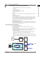
Chapter 1 Before Using the DAQSTANDARD 1.1 Overview of the DAQSTANDARD 1 2 3 Viewer Viewer displays the values and waveforms of the measured data from the recorder and prints them. Hardware Configurator Hardware Configurator is a software application for creating setup data for the recorder. It can send setup files that you have created to the recorder and save them to storage media.
1.1 Overview of the DAQSTANDARD Connection (Login) Conditions DXP (Style S4 or later) 1 2 3 4 5 6 11 16 21 26 7 12 17 22 27 8 13 18 23 28 9 14 19 24 29 10 15 20 25 30 DISP/ ENTER User name User ID Password Administrator Setup data Send setup data Receive setup data CH01 CH02 CH03 CH04 TC TC TC TC ON ON ON ON Change password • Only the administrators that are registered to the target DXP can log in.
1.
1.2 Hardware Required PC System Environment Personal Computer A computer which runs on Windows XP, Windows Vista, Windows 7, or Windows 8.
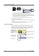
Chapter 2 2.1 Viewing and Creating Setup Data Confirming the Setup Data 1 Starting the DX-P Hardware Configurator Prints (section 2.9) Loads Setup Data Sends Setup Data Data check (section 2.7) Displays the version information This tab appears when you operate to display the login information . Menu bar Tool bar 3 4 Index Scroll the screen (up and down) Scroll the screen (left and right) Note You cannot change the contents of the imported setup file and overwrite the file.
2.1 Confirming the Setup Data Confirming the Setup Data Click this tab to open “Meas” Click this tab to open “Math” Click this tab to open “Settings” Click this tab to open “System Mode” Click this tab to open “Login Information” For the detail of the login information and the batch system settings, see next page. For the description of other settings, see sections 2.3 to 2.6. Confirming the Data Information 1. Select [Information] - [Data Information...]. 2. The [Information] dialog box opens. 3.
2.1 Confirming the Setup Data Confirming the Login Information and the Batch System Settings 1 Confirming the Login Information 2 To confirm the information other than login information and batch system settings, see section 2.2 and the following sections. 3 When the time set expires, the password change is required. Range of operations permitted (see below). Administrator: All operations User: The number shows the range of operations Click this tab to display the login information.
2.1 Confirming the Setup Data Confirming Batch System Settings 2. Click here (also selectable from [Setting] - [System Mode Setting]) 1. Select this tab. Batch system settings Login function Electronic signature function • Login user ID You are requested to enter the user ID when logging in. • Auto logout If there is no key operation for the specified time, the user is automatically logged out. If [OFF] is selected, the user is logged out only when the logout operation is performed.
2.2 Configuration 1 This operation is for creating new setup data (excluding the login information and batch system settings). Viewing and Creating Setup Data Starting Editing 2 This operation enables editing setup data. 1. Select [Edit] [Edit Configuration]. 3 2. The [Edit Data] dialog box opens. 4 Index 3. Click [OK] to start editing Note When you start editing, the login information and batch system settings are not displayed.
2.
2.3 Setting the Measurement Channels 1 Input Type and Span Mode, Range/Type Select from the list of choices from the pull-down menu. Mode VOLT TC RTD DI SKIP Range/Type 20 mV, 60 m V, 200 mV, 2 V, 6 V, 20 V, 50 V TypeR, S, B, E, K, J, T, N, W, L, U Pt100, JPt100, Cu10*, Cu25* LEVEL (voltage level), CONT (Contact) None 2 3 * /N1 option Note If SKIP is selected, settings such as Delta/Scale/Sqrt and Range/Type are discarded.
2.3 Setting the Measurement Channels Scale L, Scale U, and Decimal Point Enter the upper and lower limit values to which you wish to convert the input values. Set the decimal position by the number of digits to the right of the decimal point. When the scale L and scale U values are set to the same value or when a value outside the range is entered, they are corrected when the data are checked. Unit Clicking the unit display area enables entering a new unit. Enter the unit using up to six characters.
2.3 Setting the Measurement Channels Graph 1 Divisions Select the number of scale divisions. 2 Bar Graph Viewing and Creating Setup Data Select the reference position of the bar graph. Selecting [Center] when the bar graph is vertical produces no effect. It is set back to [Normal] when the data are checked. 3 Scale When using scale display on the trend screen, select the position to display the scale. For details related to divisions, bar graph, and scale, see section 5.
2.3 Setting the Measurement Channels Copying and Pasting Setup Data The items checked in [Copy Details] can be copied and pasted. Click the channel number to select the copy source or paste destination. To select multiple channels to be copied, drag the channel number to specify the range to be copied. To select multiple copy destinations, select the range in a similar fashion. 2. The [Meas. Channel Copy Details] dialog box opens. 1. Click here. 6. Click here. 5. Select the copy source. 3.
2.4 1 Set the display span. Enter the unit (6 characters or less). Enter the constant to be used in the expression. 2 Double-click when setting each channel. Turn ON/OFF computation. Select this tab. Enter the expression Viewing and Creating Setup Data Setting the Computation Channels (/M1 Option) 3 4 Select the number of digits to the right the decimal. Set the alarm (section 2.3). Index Tools (section 2.3) Alarm delay time Enter the tag (section 2.3). Waveform display zone (section 2.
2.4 Setting the Computation Channels (/M1 Option) Display Span Alarm Tag Sets the upper and lower limits of the display. The range is from –9999999 to 99999999. Set the number of digits to the right the decimal to four digits or less. You can set up to 4 alarms on each computation channel. The alarm types are upper limit alarm (H), lower limit alarm (L), delay upper limit alarm (T), and delay lower limit alarm (t). For details, see section 2.3. The settings are the same as the measurement channels.
2.4 Setting the Computation Channels (/M1 Option) Setting One Computation Channel at a Time The items in the [Math] tab can be configured for each channel. The items that are configured are the same as those configured on the spreadsheet. For details, see pages 2-11 and 2-12. 3 4 1. Double-click the channel you wish to set. 2. The channel setting dialog box opens. Index 4. After setting the items, click here. Set the maximum value. Set the minimum value. Copy the first setting.
2.5 Configuring the Engineering Mode Screen Display Select this tab. Select the time per division Select the display direction of the trend and bar graphs. Set the screen background color to white or black. Line width 1 to 3 dots On: Use Off: Not use The backlight saver function is activated, when there is no key operation or alarm occurrence for the “Saver time.” Recovers by a key operation or alarm occurrence. Recovers by a key operation.
2.5 Confiuring the Engineering Mode Message/File Click here (also selectable from [Setting] [Engineering Mode Setting]). Select the group. Enter the group name. Enter the message. Copy and paste the message. 1 2 Viewing and Creating Setup Data 3 4 Index Enter the comment. Enter the save destination folder. Resets the range selection. Message number Note Messages 1 to 8 of the message group 7 can be assigned to the USER key and the remote control function (option, /R1).
2.5 Confiuring the Engineering Mode Group/Trip Line Click here (also selectable from [Setting] - [Engineering Mode Setting]). Select the tab of the group to be configured. Enter the group name. Turn ON/OFF the trip line display. Check the channels that you wish to register to the selected group (blue: ON). Set the trip line by dragging. Set the trip line by entering a value. Select the color of the trip line. Group Name Up to 16 characters can be entered for the group name.
2.5 Confiuring the Engineering Mode Click here (also selectable from [Setting] - [Engineering Mode Setting]) Enter the view group name. Select the type of screen from the menu or drag & drop the screen. 1 2 Viewing and Creating Setup Data 3 4 Index Select the group. Types of screens available USER Key and Daylight Saving Click here (also selectable from [Setting] - [Engineering Mode Setting]). Select the function to be assigned to the USER key.
2.5 Confiuring the Engineering Mode Batch Click here (also selectable from [Setting] - [Engineering Mode Setting]). Automatically increase the lot number by 1 at Memory Stop. Use the lot number indication. Header 1 to 3 Enter character strings (up to 64 characters) that are written to the batch and continuous data files. Calibration Correction Can only be specified on measurement channels. Click here (also selectable from [Setting] - [Engineering Mode Setting]). Select channel.
2.6 Configuring the System Mode 1 Alarm/Relay/Remote 2 Viewing and Creating Setup Data 2. Click here (also selectable from [Setting] - [System Mode Setting]). 1. Select this tab. 3 4 Remote control terminal number Resets the range selection. Copy and paste the selected range (see page 4-15). Select actions. Alarm/Relay • Reflash When multiple alarms are set to one alarm output relay, this function notifies the succeeding alarms after the first alarm that causes the relay activation.
2.6 Configuring the System Mode Remote (Option, /R1) You can assign items to be controlled by the eight remote control terminals. This is possible, if the remote function is available. Scan Interval/Memory/Memory Timeup Click here (also selectable from [Setting] - [System Mode Setting]). Check the channels you wish to sample. Resets the range selection. Select the range. Turn ON/OFF at once. Set these parameters when the data type is set to [EVENT & DISP] or [EVENT].
2.6 Configuring the System Mode 1 Memory Timeup Specify the date and time to save the data in the internal memory to the external storage medium. • Timeup type 2 • Date Date (1 to 28) or the day of the week (SUN, MON, TUE, WED, THU, FRI, and SAT) • Time (Hour) Hours (00 to 23) Channel (Setting the Burnout and RJC) Click here (also selectable from [Setting] - [System Mode Setting]). Set to the positive side (100%). Set to the negative side (0%).
2.6 Configuring the System Mode Application Click here (also selectable from [Setting] - [System Mode Setting]). Check here if you wish to clear the waveform display and start data acquisition. Select the type of process. Application Batch: You can sign the batch data in batch units. Continue: You can sign the continuous data in units of file Timer (/M1 Option) Click here (also selectable from [Setting] - [System Mode Setting]). Select one. Select whether or not use [Save Data].
2.6 Configuring the System Mode 1 Reset Reset the results of TLOG computation when the timer expires. Save Data Report (Creating Hourly/Daily/Weekly/Monthly Reports, Option) 2 Viewing and Creating Setup Data Measured/computed data of all channels can be saved to the external storage medium at intervals specified by a timer (TLOG data). 3 Click here (also selectable from [Setting] - [System Mode Setting]). Set the date and time at which to create the report.
2.6 Configuring the System Mode Temperature Unit, Time Zone, Time deviation limit, System Relay and Auxiliary Functions Click here (also selectable from [Setting] - [System Mode Setting]). Temperature Unit Select the °C or °F for the temperature unit. GMT (Time Zone) Set the time difference from the GMT.
2.6 Configuring the System Mode 1 • Displayed Language Select the language to be used on the display. • Partial Expanded Display If the partial expanded display is set to [Not], the partial expanded display settings of the Meas/Math tab are void. Viewing and Creating Setup Data • Remote Controller ID (/KB1, /KB2 option) 2 Select the remote controller ID from [0] to [31]. Select [Off] if you do not use the remote control terminal.
2.6 Configuring the System Mode Network The “Memory Data Out” setting is void on the DX100P/DX200P. Setting the TCP/IP 1. Click here (also selectable from [Setting] - [System Mode Setting]) 2. Select this tab Set the IP address Set these addresses when using the DNS DNS setting Enter the timeout value when turned ON You must set the DNS, if you are using a host name to specify the destination server of the file transfer on an FTP client or the server of the e-mail recipient.
2.6 Configuring the System Mode 1 FTP Connection Specify the primary and secondary file transfer destinations (FTP servers). 2. Select the primary or secondary tab. 1. Select this tab. 2 Viewing and Creating Setup Data 3 Select the file transfer destination 4 Index • Server Name Set the FTP server name using up to 64 alphanumeric characters. You can also specify the IP address. In this case, DNS is not necessary.
2.6 Configuring the System Mode Setting the Serial Communication • Data Length Select the data length from the following list. Make sure to select 8 bits when outputting data in binary format. • RS232 Handshaking Select the handshaking method from the following list. This setting is valid only for the RS-232 interface. • RS-422A/485 Address Select the address from 1 to 32. This setting is valid for the RS-422A/485 interface and the Modbus protocol.
2.6 Configuring the System Mode Setting the Modbus Master 1 Set the command. 2 Viewing and Creating Setup Data 3 4 Index Data type Register No. (slave device) Address (slave device) Communication input data (DX100P: C01 to C12, DX200P: C01 to C30) Select whether or not use command. • Basic Read cycle: The cycle at which data is read from other devices.
2.6 Configuring the System Mode Setting the Web Server Operator page Monitor page Select whether or not use the Web server. Select whether or not use Monitor/Operator page. • Access control/User name/Password Select whether or not use the access control. To use the access control, enter the user name (up to 20 characters) and password (up to 8 characters) to display the operator or monitor page.
2.6 Configuring the System Mode 1 Setting the E-Mail Transmission Transmit e-mail when alarm occurred/released. Transmit e-mail at specified time. Transmit e-mail when storage medium error, etc. are detected. Transmit e-mail when creating a report. 2 Viewing and Creating Setup Data 3 4 Select the recipient Select the alarm Transmit e-mail when creating a report.
2.6 Configuring the System Mode Setting SNTP SNTP server function SNTP client function • Basic • SNTP server Select [ON] when using the SNTP server function. The DXP sends time information to SNTP clients on the network. • SNTP client Select [ON] when using the SNTP client function. The DXP queries time information to an SNTP server on the network. • Server name Set the access destination of time information using up to 64 alphanumeric characters. Set the server host name or IP address.
2.7 Adjusting the Setup Data (Checking the Data) Checking the Setup Data 2 1. Click here ([System] - [Data Adjustment]). 3 or 2. If the data are not consistent, the [Data Adjustment] dialog box opens (see the description below). 4 Click here to display the correction list The data are corrected in the following cases: • When the values of the items of the Meas/Math tab are outside the range.
2.8 Saving the Setup Data Saving the Setup Data Saves the setup data b specifying the save destination and file name. 1. Select [File] - [Save As]. 2. The [Save As] dialog box opens. 3. Set the destination and file name and click here Note • • 2-34 You cannot save the data using the same file name as the file in the save destination (overwriting the file is not allowed). You cannot edit the setup data after saving it.
2.9 Printing the Setup Data 1 Setting the Printer 2 1. Select [File] - [Print Setup]. Viewing and Creating Setup Data 3 4 Index 2. Set the printer, paper and orientation. Note Set the printer according to the environment of the system that you are using. Print Preview You can preview the print layout before actually printing the data. Selecting [File] - [Print Preview] displays the print preview screen. Printing 1. Click here ([File] - [Print]). 2.
2.10 Characters That Can Be Used The characters in the following table can be used when entering a group name, a view group name, a message, a comment to the file header, a save destination directory name, and parameters such a the user name, user ID, and password for signing. SP 0 A K U a k u # 1 B L V b l v _ % 2 C M W c m w ( ) 3 D N X d n x 4 E O Y e o y * 5 F P Z f p z + 6 G Q 7 H R . 8 I S / 9 J T g q h r i s j t @ Note (*), (+), (.
Chapter 3 Receiving and Sending Setup Data 3.1 Connecting to the DXP 1 Notes about Sending and Receiving 2 Note • • • • • Password 4 Index Note Default password For the following cases, enter the default password in the Password box. • Connecting for the first time after user registration. • Connecting for the first time after resetting the password because the user was invalidated. User Administrator 1 to 3 User 01 to 30 Default Password Admin1, Admin2, and Admin3 User01, User02, User03, ...
3.2 Receiving Setup Data from the DXP 1. Select [Comm.] - [Receive Setting]. 3. The [Receiving data] dialog box opens. 2. If the setup data has been edited, a save confirmation message appears. (If the data has not been edited, the Receiving data dialog box opens.) For information about saving setup data, see section 2.8. 4. Enter the IP address, user name, user ID, and password. 5. Click here. • If the password has expired, see page 3-1. Start reception after you change the password. 6.
3.3 Sending Setup Data to the DXP 1 1. Select [Comm.] - [Send Setting]. 2 3 2. The [Sending data] dialog box appears. Receiving and Sending Setup Data 4 Index 3. Enter the IP address, user name, user ID, and password. 4. Click here. • If the password has expired, see page 3-1. Start sending after you change the password. 5. A progress indicator appears. • If the data cannot be sent, an error message appears. 6. The message “Sending finished” appears and the received setup data is displayed.
Chapter 4 Troubleshooting 4.1 Messages and Corrective Actions 1 Messages may appear on the screen during operation. This section explains the meanings of the error messages and how to respond to them. 2 Error Messages Code E7001 E7002 Message Unreadable file Failed to open file. E7003 E7004 Failed to make file. A user is already logged in. Unable to login now. E7006 E7007 E7008 Password is incorrect. No system administrator’s privilege. The number of connection has been exceeded.
4.1 Messages and Corrective Actions Warning Messages Code W7051 Message Save changes to NewFile? W7052 W7053 File already exist. System configuration has been changed. The input configuration and data will be initialized. Continue? Initialize current settings. Edit this configuration? W7054 W7055 Corrective Action/Explanation The setup information has been changed, but the file has not been saved. Choose whether or not to save the file. Specify a different file name.
Index Index 1 A H A/D integrate......................................................................... 2-20 active storage change........................................................... 2-25 alarm............................................................................. 2-8, 2-19 alarm delay.............................................................................. 2-8 alarm indicator....................................................................... 2-19 alarm value.....................
Index system configuration............................................................... 2-2 system relay.......................................................................... 2-24 T text message on cal correct.................................................. 2-25 times...................................................................................... 2-12 time zone............................................................................... 2-24 TLOG.............................................