
User Manual


2-9
SM 04L31A01-01E
Testing
2
Test of Storage Drive
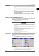
1. Insert a formatted disk into the drive of the UUT.
2. In the set mode*1, choose Save/Load, Clear data, and then Save settings. Save
the current panel conditions under a desired filename.
3. In the set mode, choose Save/Load, Clear data, and then File list. Verify that the
file saved in step 2 exists in the list.
Test of Alarm Relay Contact Outputs (applicable to option codes /A6, /A6R, /A4F and /
A4FR)
Insulation Resistance and Withstanding Voltage Tests
Item Measured Point Specification
Insulation resistance No less than 20 MΩ at 500 V DC
Withstanding voltage As above
Between relay output terminals and
grounding terminal
Free from damage after applying 1500 V AC,
50/60 Hz for 1 minute (with breaking leakage
current set to 2 mA)
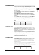
Alarm Actions
1. Prepare the same input terminals and settings as step 1 in “Digital Output”
(page 2-8), and also adjust the alarm relay output as follows:
Alarm
(Level 1)
Relay Output
On/off
No.
Ixx
where xx: alarm
output number to test
2. Verify that an alarm contact works as follows upon turning on/off the
corresponding relay output.
Terminals Normal Remarks
NO–C Break Where the output relay action is set to
normally de-energized (factory set)NC–C Make
During Alarm
Make
Break
Test of Remote Control (applicable to option codes /A6R and /A4FR)
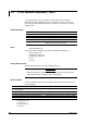
Insulation Resistance and Withstanding Voltage Tests
Item Measured Point Specification
Insulation resistance Between remote control terminals and
grounding terminal
No less than 20 MΩ at 500 V DC
Withstanding voltage As above
Free from damage after applying 500 V DC for 2
minute (with breaking leakage current set to 2 mA)
Remote Control Actions
Assign individual functions to 8 remote control inputs, then short-circuit each of those
inputs in turn and verify that the CX1000/CX2000 is controlled as specified.
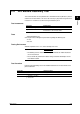
Test of 24 VDC Transmitter Power Output (applicable to option code /TPS4)
Test of Insuration Resistance and Withstanding Voltage
Withstanding voltage
Insulation resistance Between 24 VDC output terminals and
grounding terminal
As above
Between 24VDC output terminals
No less than 20 MΩ at 500 VDC
Free from damage after applying 500 VAC, 50/60 Hz for
1 minute (with breaking leakage current set to 10 mA)
Free from damage after applying 500 VAC, 50/60 Hz for
1 minute (with breaking leakage current set to 10 mA)
2.2 Test Procedures