
User Manual


2-3
SM 04L31A01-01E
Testing
2
2.2 Test Procedures
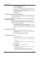
Insulation Resistance Test
Perform this test using a DC 500 V insulation resistance meter and confirm that the
results meet the criteria below.
Terminals Reference Values Notes
Power terminal to earth terminal 100 MΩ or higher Short all channels prior to test
Measurement input terminal to
earth terminal
Control input terminal to earth
terminal
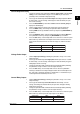
RS-422-A/485 SG terminal to 100 MΩ or higher Test only if the basic
RS-422-A/485 FG terminal specification code for the
communications port is -2.
Ethernet input/output terminal 100 MΩ or higher Short all terminals prior to test
to earth terminal
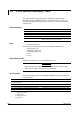
Withstand Voltage Test
Perform the test using a withstanding voltage tester and confirm that the results meet the
criteria below, and that the instrument does not malfunction.
Terminal Reference Values
AC power terminal to earth terminal* Leakage current of 10 mA or less at 1.5 kV AC for 1 minute
DC power terminal to earth terminal (/P1)* Leakage current of 10 mA or less at 0.5 kV AC for 1 minute
Measurement input terminal to earth terminal
†
Leakage current of 2 mA or less at 1.5 kV AC for 1 minute
Control input terminal to earth terminal
†
Leakage current of 2 mA or less at 1.5 kV AC for 1 minute
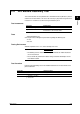
Between measuring input terminals
‡
Leakage current of 1 mA or less at 1 kV AC for 1 minute
Between control input terminals
‡
Leakage current of 1 mA or less at 1 kV AC for 1 minute
Current and voltage pulse to earth terminal
§
Leakage current of 2 mA or less at 1 kV AC for 1 minute
Control relay terminal to earth terminal Leakage current of 2 mA or less at 1.5 kV AC for 1 minute
(2, 4, and 6 loop models)
||
DO relay terminal to earth terminal Leakage current of 2 mA or less at 1.5 kV AC for 1 minute
(2, 4, and 6 loop models)
#
DO(Tr) terminal to earth terminal Leakage current of 2 mA or less at 0.5 kV AC for 1 minute
(2, 4, and 6 loop models or /CST1)**
D1 terminal to earth terminal Leakage current of 2 mA or less at 0.5 kV AC for 1 minute
(2, 4, and 6 loop models or /CST1)
††
Alarm relay terminal to earth terminal Leakage current of 2 mA or less at 1.5 kV AC for 1 minute
(/A6, /A6R, /A4F, /A4FR)
‡‡
Remote terminal to earth terminal (/A6R, /A4FR)
§§
Leakage current of 2 mA or less at 0.5 kV AC for 1 minute
24 V transmitter power supply output to earth terminal Leakage current of 10 mA or less at 0.5 kV AC for 1 minute
(/TPS4)
||||
* Short L and N (or +/– with the /P1 option)
† Short all channels
‡ Short the + and – input terminals (except for the RTD b terminal)
Short the even and odd channels (for example, short channels 1-3-5 and 2-4-6 on the CX1000 or channels 1-3-
5-7-9 and channels 2-4-6-8-10 for the CX2000), and test the withstanding voltage between them.
§ Short mA, PULS, and C.
|| Short NO, NC, and C on CTRL OUT.
# Short 1NO, 1C, and 2NO on DO.
** Short DO3—DO6 and C.
†† Short all DI terminals.
‡‡ Short all alarm relay terminals.
§§ Short all remote terminals.
|||| Short all transmitter power supply output terminals (+/–).