
Instruction Manual


4-1
IM 04L31A01-17E
4
Modbus Protocol
4.1 Modbus Protocol Specifications
The Modbus protocol can be used over the serial interface (RS-232 or RS-422/485).
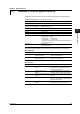
The Modbus specifications of the CX are as follows.
Specifications Description
Transmission media RS-232 or RS-422/485
Control RS-232: None only
(Flow control is not available.) RS-422/485: None only
Baud rate 1200, 2400, 4800, 9600, 19200, and 38400
Start bit Fixed to 1 bit
Stop bit Fixed to 1 bit
Parity Select Odd, Even, or None (no parity).
Transmission mode RTU (Remote Terminal Unit) mode only
• Data length 8 bits
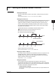
• Data interval 24 bits or less*
• Error detection Uses CRC-16
* Determines message termination with a time interval equal to
3.5 characters or more.
Slave address RS-232: 1 to 32
RS-422/485: 1 to 32
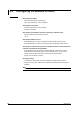
The function codes of Modbus protocol that are supported by the CX are as follows
Master Function
Function Code Function Operation
3 Reads the hold register The CX reads the data in the hold
(4xxxx and 4xxxxx) register of another device.
4 Reads the hold register The CX reads the data in the input
(3xxxx and 3xxxxx) register of another device.
Slave Function
Function Code Function Operation
3 Reads the hold register The master device can read the
(4xxxx) communication input data written using
function codes 6 and 16.
4 Reads the input register The master device reads the computed,
(3xxxx) measured, control, and time data of the CX.
6 Single-write to the hold register The master device writes to the register of
(4xxxx) the CX.
8 Loopback test The master device performs a loopback test
of the CX. The CX only supports message
return (test code 0x00*).
16 Writes to the hold register The master device writes to the
(4xxxx) communication input data of the CX.
* Hexadecimal “00”.
Chapter 4 Modbus Protocol