
Instruction Manual

3-5
IM 04L31A01-17E
Serial Interface
3
3.3 Terminal Arrangement and Signal Names and
the Connection Procedure of the RS-422/485
Interface
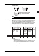
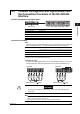
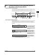
Terminal Arrangement and Signal Names
(Rear panel)
FG SG SDB SDA RDB RDA
FG (Frame Ground) Case ground of the CX.
SG (Signal Ground) Signal ground.
SDB (Send Data B) Send data B (+)
SDA (Send Data A) Send data A (-)
RDB (Received Data B) Receive data B (+)
RDA (Received Data A) Receive data A (-)
Connection Procedure
Cable
There are two types of cables available, the four-wire cable and the two-wire cable (used
only for the Modbus protocol). The cable should meet the following specifications.
Cable Shielded twisted pair cable
3 pairs 24AWG or more (four-wire), 2 pair 24AWG or more (two-wire)
Characteristic impedance 100 Ω
Capacitance 50 pF/m
Cable length Up to 1.2 km*
* The transmission distance of the RS-422/485 interface is not the straight-line distance, but rather
the total length of the (shielded twisted-pair) cable.
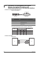
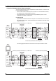
Connecting the Cable
As shown in the following figure, attach a crimp-on lug with isolation sleeves for 4 mm screws
to the end of the cable. Keep the exposed section from the end of the shield within 5 cm.
FG SG SDB SDA RDB RDA
Shield potential
Two-wire
Shield
FG SG SDB SDA RDB RDA
Shield potential
Four-wire
Shield
WARNING
To prevent the possibility of electric shock, connect the cables with the power
turned OFF.
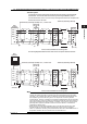
Note
• As shown on the next page, connect the RD pin to the SD (TD) pin on the PC (converter) side
and the SD pin to the RD pin on the PC side.
• The two-wire cable can be used only when using the Modbus protocol.