
Instruction Manual

3-2 IM 04L31A01-17E
3.2 Connector Pin Arrangement and Signal
Names, Connection Procedure, and
Handshaking Methods of the RS-232 Interface
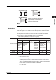
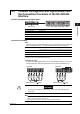
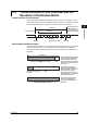
Connector Pin Arrangement and Signal Names
Connector Pin Arrangement
2
1 3
4 5
6
7
9
8
(Rear panel)
Pin No. Signal Name Meaning
2 RD (Received Data) Received data from the PC. Input signal to the CX.
3 SD (Send Data) Transmitted data to the PC. Output signal from the CX.
5 SG (Signal Ground) Signal ground.
7 RS (Request to Send) Handshaking signal when receiving data from the PC.
Output signal from the CX.
8 CS (Clear to Send) Handshaking signal when transmitting data to the PC. Input
signal to the CX.
* Pins 1, 4, 6, and 9 are not used.
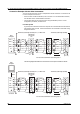
Serial (RS-232) Standard Signals and Their JIS and ITU-T Abbreviations
Pin No.
(9-pin connector)
Abbreviation
RS-232
Description
ITU-T
JIS
5
3
2
8
7
AB (GND)
BA (TXD)
BB (RXD)
CB (CTS)
CA (RTS)
102 SG
103
104
106
105
SD
RD
CS
RS
Signal ground
Transmitted data
Request to send
Received data
Clear to send
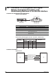
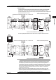
Connection Procedure
Signal Direction
PC CX
RS [Request to send]
SD [Send data]
RD [Receive data]
2
3
8
7
CS [Clear to send]