
Instruction Manual


9-11
IM 04L31A01-17E
9
Green Series Communications
Setting the Modbus Address
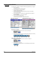
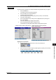
10. Use the arrow keys to move the cursor to the [Modbus address] box.
11. Press the [Input] soft key. An entry box (numeric value input pop-up window)
appears.
12. Enter the Modbus address of the controller.
13. Press the DISP/ENTER key. On the CX1000, select [ENT] and then press the
DISP/ENTER key.
The Modbus address that you entered is displayed in the [Modbus address] box.
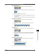
Selecting the Connecting Model
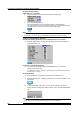
14. Use the arrow keys to move the cursor to the [Connecting model] box.
15. Press one of the soft keys from [UT320] to [ETC] to select the connecting
model.
Selecting the Loop
16. Use the arrow keys to move the cursor to the [Loop select] ([Select] on the
CX1000) box.
17. Press the [First] or [Second] loop soft key to select the loop to be used. For
UT320 to UT450, select only [First]. For UT520 to UT750, select [First] or
[Second].
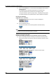
Entering the Tag and Tag Comment
18. Use the arrow keys to move the cursor to the [Tag] or [Tag comment] box.
19. Press the [Input] soft key. An entry box appears.
20. Enter the tag or tag comment in the entry box.
9.4 External Loop Setting > Basic Setting