
Instruction Manual


9-8 IM 04L31A01-17E
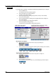
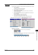
• Control mode
• If the connecting model is UT series, select from the below. However, the selectable
items vary depending on the connecting model. See the UT Series user’s manual.
Control Mode Soft Key Menu*
Single-loop control SingleLoopControl
Cascade-primary loop control CascadePrimaryLoop
Cascade secondary-loop control CascadeSecondaryLoop
Cascade control CascadeControl
Loop control for backup ControlBackUp
Loop control with PV switching PVSwitching
Loop control with PV auto-selector PVAutoSelector
Loop control with PV-hold function PVHoldFunction
Dual loop control DualLoopControl
Temperature and Humidity control Temperature-Humidity
Cascade control with two universal inputs Cascade-2Uni
Loop control with PV switching and two universal inputs PVSwitching-2Uni
Loop control with PV auto-selector and two universal inputs PVAutoSelector-2Uni
* Some of the dislayed characters are abbreviated even further on the CX1000.
• If the connecting model is “ETC,” you cannot select the control mode.
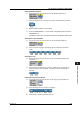
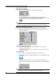
• The status display on the operation display of the CX and the soft key menus vary
depending on the UT series model and control mode as shown below.
SingleLoopControl
SingleLoopControl
SingleLoopControl
SingleLoopControl
CascadePrimaryLoop
CascadeSecondaryLoop
CascadeControl Primary
Secondary
ControlBackUp
PVSwitching
PVAutoSelector
PVHoldFunction
SingleLoopControl
CascadePrimaryLoop
CascadeSecondaryLoop
CascadeControl Primary
Secondary
ControlBackUp
PVSwitching
PVAutoSelector
DualLoopControl 1st
2nd
Temperature-Humidity 1st
2nd
Cascade-2Uni Primary
Secondary
PVSwitching-2Uni
PVAutoSelector-2Uni
Y
Y
Y
Y
Y
Y
Y
Y
Y
Y
Y
Y
Y
Y
Y
Y
Y
Y
Y
Y
Y
Y
Y
Y
Y
Y
Y
Y
Y
Y
Y
Y
Y
Y
N
Y
Y
Y
Y
Y
Y
Y
Y
N
Y
Y
Y
Y
Y
Y
Y
Y
N
Y
Y
Y
Y
Y
Y
Y
Y
N
Y
N
Y
Y
Y
Y
Y
Y
N
Y
N
Y
Y
Y
Y
Y
Y
Y
Y
N
Y
Y
N
N
Y
Y
N
N
N
N
N
N
N
Y
Y
Y
N
Y
N
Y
Y
Y
Y
Y
Y
Y
Y
N
Y
Y
Y
Y
Y
Y
Y
Y
N
Y
Y
Y
Y
Y
Y
Y
Y
N
Y
Y
Y
Y
Y
Y
Y
Y
N
Y
Y
Y
Y
Y
Y
Y
Y
Y
N
Y
Y
Y
Y
Y
Y
Y
Y
N
Y
Y
Y
Y
Y
Y
Y
Y
N
Y
Y
Y
Y
Y
Y
Y
Y
Y
Y
Y
Y
Y
Y
Y
Y
Y
Y
Y
Y
Y
Y
Y
Y
Y
Y
Y
Y
Y
Y
Y
Y
Y
Y
Y
Y
Y
Y
Y
Y
Y
Y
Y
Y
Y
Y
Y
Y
Y
Y
Y
Y
Y
Y
Y
Y
Y
Y
Y
Y
Y
Y
Y
Y
Y
Y
Y
Y
Y
Y
Y
Y
Y
Y
Y
Y
Y
Y
Y
Y
Y
Y
Y
Y
Y
Y
Y
Y
Y
Y
Y
Y
Y
N
Y
Y
Y
Y
Y
Y
Y
Y
N
Y
Y
Y
Y
Y
Y
Y
Y
N
Y
Y
Y
Y
Y
Y
Y
Y
Y
Y
Y
Y
Y
Y
Y
Y
Y
Y
Y
Y
Y
Y
Y
Y
Y
Y
Y
Y
Y
Y
Y
Y
Y
Y
Y
Y
Y
Y
Y
Y
Y
Y
Y
Y
Y
Y
Y
Y
Y
Y
Y
Y
Y
Y
Y
Y
Y
Y
Y
Y
Y
Y
Y
Y
Y
Y
Y
Y
Y
Y
Y
Y
Y
Y
Y
Y
Y
Y
Y
Y
Y
Y
Y
Y
Y
Y
Y
Y
Y
Y
Y
Y
Y
Y
Y
Y
Y
Y
Y
Y
Y
Y
Y
Y
Y
Y
Y
Y
Y
Y
Y
Y
Y
Y
Y
Y
Y
Y
Y
Y
Y
Y
Y
Y
Y
Y
Y
Y
Y
Y
Y
Y
Y
Y
Y
Y
Y
Y
Y
Y
Y
Y
Y
Y
Y
Y
Y
Y
Y
Y
Y
Y
Y
Y
Y
Y
Y
Y
Y
Y
Y
Y
Y
Y
Y
Y
Y
Y
Y
Y
Y
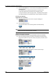
UT3 0
UT3 1
UT4 0
UT5 0
UT750
Control Mode (UT Mode) MODE
Dsp. Opr. Dsp. Opr. Dsp. Opr. Dsp. Opr. Dsp. Opr. Dsp. Opr. Dsp. Opr. Dsp. Opr.
REM/LOC RUN/STP
SP OUT
AUTO TUN
SP NO.
GROUP NO.
Model
Dsp.: Indication on the display (Y/N)
Opr.: Function key display for control at the lower section of the display (Y/N)
9.4 External Loop Setting > Basic Setting