
Instruction Manual

7-37
IM 04L31A01-17E
7
Response
Note
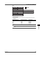
• Information for skipped measurement channels, computation channels when
computation is turned OFF, and control channels when control is turned OFF is not
output.
• Alarm setting values for control channels set by loops are output as alarm information
for the PV, SP, and OUT channels corresponding to the alarm types.
• When alarms are OFF, 0 is output for the alarm setting.
• If the alarm type is 0 in the control groups (control alarm OFF), an alarm value of 0 is
output as alarm information for the PV channels.
• Information for channels belonging to loops set for analog retransmission are not
output.
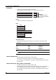
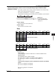
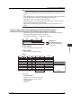
Output of Upper/Lower Limit of Input Span and Decimal Point Position for
Measurement/Computation/Control Channels (Style number S3 or later)
• Upper/lower limit of input span and decimal place for measurement/computation/
control channels are output using the FT command.
• The output format identifier is 1. See page 7-3, “Identifier.”
2 bytes
Number of blocks
Block 1
Number of bytes
2 bytes
BINARY data
(The BINARY data section
on the “Conceptual diagram”
on page 7-2.)
Number of Blocks
This is the number of blocks (fixed at 0.)
Number of Bytes
This is the size of one block in bytes.
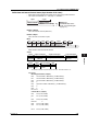
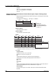
Blocks
Year Month
Month
(Reserved)*
• • •
(Reserved)*
• • •
(Reserved)*
• • •
(Reserved)*
• • •
Hour
Decimal P. P
• • •
Decimal P. P
• • •
Decimal P. P
• • •
Decimal P. P
• • •
Minute Millisecond
Second
Span(Upper limmit)
• • •
1 byte 1 byte 1 byte 1 byte 1 byte 1 byte
2 bytes
4 bytes
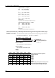
Measurement channel
• • •
Computation channel
• • •
Control channel
• • •
Channel(Green Series)
• • •
Span(Upper limmit)
• • •
Span(Upper limmit)
• • •
Span(Upper limmit)
• • •
Span(Lower limmit)
• • •
Span(Lower limmit)
• • •
Span(Lower limmit)
• • •
Span(Lower limmit)
• • •
2 bytes
Decimal P. P: Decimal point position
Data details
Channel Numbers
CX2000:1-20, 31-60, 101-118, 201-248
CX1000:1-3, 31-48, 101-106, 201-212
Unused Region
Fixed at 0
7.3 Output Format of BINARY Data