
Instruction Manual


4-13
IM 04L31A01-17E
4
Modbus Protocol
4.5 Communications as a Modbus Slave
This section explains the command messages used when setting the CX to Modbus
slave and communicating with a Modbus master device. By sending a command
message from a Modbus master device, the input registers of the CX can be read and
the hold registers can be read or written.
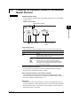
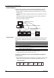
Command Message Construction
Below is the construction of command messages sent from a Modbus master device to
the CX.
Slave Address Function Code Data Error Check
Slave Address
Specify the address of the Modbus slave device to communicate with. The slave
address on the CX is set in the range of 1 to 32 (selected in the serial interface
settings). The command messages from a master device are received by all the
Modbus slave devices that are connected. However, only the slave device with the
matching address reads the message and returns data.
Function Code
Specifies the command (function code) from the Modbus master.
Data
Specifies parameters such as the internal register (D register) number and quantity
according to the function code.
Error Check
Error check is performed using cyclic redundancy check (CRC-16).
Specifying the Register Number
Following the function code, data that is required by the Modbus slave device in
executing the function is transmitted. The data includes the register number to which a
read or write operation is to be executed.
The following table shows the assignment of the reference number to each register on
the CX.
Item Reference Number
Input register 3xxxx
Hold register 4xxxx
If the Modbus master device is to specify the input register or the hold register using a
command message, the register is specified using a relative number with respect to the
reference number. If the reference number of the item to be specified is 4xxxx, the
relative number with respect to this reference number is the number obtained by
subtracting 40001 from 4xxxx. For example, if the reference number of the input register
to be specified is 30100, the relative number is 99.
Reference Number Relative Number
30100 30100–30001 = 99
Note
For information on the contents of the input registers and hold registers, see appendix 6.