
Manual


Table Of Contents
- Software License Agreement
- How to Use This Manual
- Contents
- Chapter 1 Overview
- Chapter 2 Operating Procedure
- Chapter 3 Error Messages and Corrective Actions
- Index
2-7
IM WX1-06E
1
2
3
Index
Operating Procedure
Note
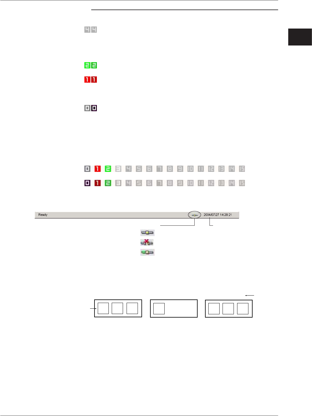
• The color of the unit numbers under Communication Status indicates the following
conditions.
Gray (characters in dark gray):
There is no IP address or host name specified
for the MX100/MW100 with that unit number
(specification is blank). Or, there is an IP address
or host name specified but the number of channels
and system is not specified.
Green: Communication with the MX100/MW100 is normal,
and data is being monitored.
Red: There is an IP address or host name specified for
the MX100/MW100 with that unit number, but the
connection failed. Or, communication was cut while
monitoring data, and now attempting to reconnect.
Black:
There was an IP address or host name specified for the
MX100 with the unit number and connection succeeded,
but there were no channels set to acquire data.
If the icon is displayed in red, try the connection again. If reconnection is successful, the
icon turns green and acquisition resumes.
When acquisition stops, all characters turn gray (characters in dark gray). When acquisition
resumes, registered items blink. The gray color of unregistered items remains unchanged
(characters in dark gray).
blinks.
does not change.
↓ ↓
• The status of GateMX/MW is displayed in the status bar. You can check the communication
status displayed in the Run tab.
Connection with MX100/MW100 normal
Connection with MX100/MW100 abnormal
Reconnecting with MX100s/MW100s
(only displayed during communication)
Number of connected clients
Condition status
• System numbers are assigned on the GateMX/MW System Configuration screen as shown
in the figure below. Since four monitor intervals can be specified on each MX100/MW100,
the system numbers are assigned in the range from 0 to 127.
MX100 of Unit No. 00
System No.
1
2 3
4
5
6 7
100 ms
200 ms
500 ms
100 ms
200 ms
500 ms
1 s
Monitor
interval
MX100 of Unit No. 01
MX100 of Unit No. 02
• Interval groups with the same monitor interval can be configured on the MX100 Standard
Software (See the MX100 Standard Software User’s Manual (IM MX180-01E)). A single
interval group is displayed as a single system on GateMX/MW.
2.4 Starting/Stopping Data Monitoring