Operation Guide WX1000 DAQWORX Installation & Operation Guide IM WX1000-01E 12th Edition
Contents Software License Agreement...............................................................................4 Checking the Contents of the Package................................................................8 CD Handling Guidelines.......................................................................................9 Overview of DAQWORX Installation..................................................................10 Installation Guide Installing the Software.......................................
Product Registration Thank you for purchasing Yokogawa products. Yokogawa provides registered users with a variety of information and services. Please allow us to serve you best by completing the product registration form accessible from our Web site. http://www.yokogawa.
Software License Agreement IMPORTANT - PLEASE READ CAREFULLY BEFORE INSTALLING OR USING: THANK YOU VERY MUCH FOR SELECTING SOFTWARE OF YOKOGAWA ELECTRIC CORPORATION ("YOKOGAWA"). BY INSTALLING OR OTHERWISE USING THE SOFTWARE PRODUCT, YOU AGREE TO BE BOUND BY THE TERMS AND CONDITIONS OF THIS AGREEMENT. IF YOU DO NOT AGREE, DO NOT INSTALL NOR USE THE SOFTWARE PRODUCT AND PROMPTLY RETURN IT TO THE PLACE OF PURCHASE FOR A REFUND, IF APPLICABLE. Software License Agreement 1.
Software License Agreement 4. Limited Warranty 4.1 The Software Product shall be provided to you on an "as is" basis at the time of delivery and except for physical damage to the recording medium containing the Software Product, Yokogawa and Supplier shall disclaim all of the warranties whatsoever, express or implied, and all liabilities therefrom.
Software License Agreement 7. Export Control You agree not to export or provide to any other countries, whether directly or indirectly, the Software Product, in whole or in part, without prior written consent of Yokogawa.
Thank you for purchasing DAQWORX. This guide covers the following topics. • Installing and uninstalling DAQWORX. • Examples of how to use DAQLOGGER to easily acquire data from Yokogawa Green series temperature controllers, the WT1600, and the MX100. To ensure correct use, please read this manual thoroughly before beginning operation. After reading the manual, keep it in a convenient location for quick reference in the event a question arises.
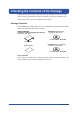
Checking the Contents of the Package Unpack the box and check the contents before operating the instrument. If some items are missing or otherwise inconsistent with the contents description, please contact your dealer or nearest Yokogawa representative. Package Contents The DAQWORX installation CD and user’s manual CD are only included if the /CD option was specified at the time of purchase.
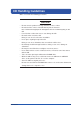
CD Handling Guidelines Make sure to take the following precautions. CAUTION • • • • • • • • • • • IM WX1000-01E Do not store the product near large amounts of refuse or dust. Do not touch the surface of the CD with no printed characters. Dirt or sweat from fingertips can damage the CD. Do not write anything on the CD. Pencil lead or residue from erasers can damage the CD. Do not bend or scratch the CD. Doing so can cause it to become unreadable. Never place anything on top of the CD.
Installation Guide Overview of DAQWORX Installation The DAQWORX installer lets you do the following: • Install the software • Add or delete software • Modify or repair a previous software installation • Install software upgrades It is recommended that you uninstall any previously installed DAQWORX components before reinstalling. During installation, only the applications that you specify are installed in the DAQWORX folder.
One or more license numbers is required during installation. Please have your license numbers ready before beginning. Your license numbers are recorded on the license sheet. 1. Place the DAQWORX installation CD in the CD-ROM drive. The installer starts. However it will not start if your CD-ROM’S Autoplay function is turned OFF. In that case, double-click the CD-ROM icon under My Computer, then double-click the Setup.exe program. Operation Guide 2. Click Next.
Installing the Software 3. After reading the entire contents of the license agreement, click I accept the terms of the license agreement or I do not accept the terms of the license agreement. If You Click “I do not accept the terms of the license agreement” 4. Click Cancel to end the installation. You may not install the software. If You Click “I accept the terms of the license agreement” 4. Click Next. The user information dialog box is displayed. 5. Enter the user name and company name.
Installing the Software installation destination, click Browse and select a new destination using the browser. When using Windows Vista, please do not install the software in a subfolder of the Program Files folder. If installed within the Program Files folder, the software will not function normally. 8. Click Next. The Base software installation screen is displayed. Installation Guide 7. Confirm that you accept the default installation destination. To change the Operation Guide 9.
Installing the Software 12. Click Next. The license number entry screen for Gate software is displayed. 13. Enter license numbers for only the number of applications you wish to use. If you are not installing any Gate software, leave the boxes blank and continue on to the next step. 14. Click Next. The Gate software selection screen is displayed. If no license numbers were entered in step 13, this screen is not displayed. 15.
Installing the Software Installation Guide 16. Click Next. The installation confirmation screen appears. Operation Guide 17. Click Next. The installation begins. When installation is complete, the Finish dialog box appears. Appendix 18. Click Finish. The dialog box closes.
Upgrading the Software To upgrade the software, you must have a separate license number for the upgrade version as well as the license number for the older version. 1. Carry out steps 1 to 7 in “Installing the Software” (page 11–13). If an earlier version of DAQWORX is installed, the windows below is displayed. If an earlier version of the software is not installed, continue on to step 3. 2. Click Next. Any free upgrades that are available will be automatically installed. 3.
Upgrading the Software Installation Guide 4. Click Next. When a License Number for a Previous Version Exists The license number entry screen for Add software is displayed. Go to step 5. When a License Number for a Previous Version Does Not Exist A screen such as the one below is displayed. Operation Guide 5. Enter the old license number. If the old license number is a 3-numeric block combination, enter the old license number in the box leaving the second block blank. 6. Click Next.
Upgrading the Software 8. Click Next. When a License Number for a Previous Version Exists The installation screen for Gate software is displayed. Go to step 10. When a License Number for a Previous Version Does Not Exist A screen such as the one below is displayed. 9. Enter the old license number. If the old license number is a 3-numeric block combination, enter the old license number in the box leaving the second block blank. 10. Click Next. The installation screen for Gate software is displayed.
Installation Guide Modifying, Repairing, or Deleting Software To modify, repair, or delete software, enter maintenance mode by performing the following procedure. • Rerun the DAQWORX installation CD. • Select Change or Delete under Add/Remove Programs. 1. The program enters maintenance mode. The Welcome dialog box opens. 2. Select Modify, Repair, or Delete.
Modifying, Repairing, or Deleting Software 3. Click Next. The Base software dialog box opens. Note The license numbers of the installed applications are displayed. 4. Enter the license numbers of applications to be added or upgraded, and select the check boxes of any applications that you wish to delete. Delete: Uninstall applications that have been previously installed. 5. Click Next.
Modifying, Repairing, or Deleting Software Installation Guide 6. Enter the old license number. 7. Click Next. The license number entry dialog box for Add software is displayed. Operation Guide Note The license numbers of the installed applications are displayed. 8. Enter the license numbers of applications to be added or upgraded, and select the check boxes of any applications that you wish to delete.
Modifying, Repairing, or Deleting Software 10. Click Next. The license number entry dialog box for Gate software is displayed. 11. If you have new license numbers to add, enter them in the boxes. If you wish to delete licenses, select the appropriate Delete check boxes. Note The license numbers of the installed applications are displayed and can be edited. 12. Click Next. The Gate software addition check boxes are displayed. 13. Select the Gate software applications you wish to add. 14.
List of User's Manuals The DAQWORX user’s manual CD contains the following manuals in PDF format. Please read the appropriate manuals for the applications you plan to use.
Viewing the User’s Manual When using Windows Vista, the following screen appears. Click Run startup.exe. The user’s manual selection screen opens. 2. Double-click the name of the manual you wish to use. The selected user’s manual is displayed. Note To display a user’s manual, Adobe Reader 7.0 or later must be installed on your PC. 3. Click OK. The dialog box closes.
Operation Guide DAQWORX allows users to assemble a data acquisition system using Yokogawa recorders, data loggers, the temperature controllers, measuring instruments without the need for programming. For adding functionality, DAQWORX offers an integrated data acquisition software system, allowing customers to connect high added-value software to their existing data acquisition systems to easily expand the range of supported applications.
Introduction to Functions The following sections provide a brief explanation of how GateMODBUS can be used to acquire data from the UT351 temperature controller on DAQLOGGER, how GateWT can be used to acquire measured data from Yokogawa’s WT1600 on DAQLOGGER, how GateMX/MW can be used to acquire measured data from Yokogawa's MX100 Data Acquisition Unit, how measured data from Yokogawa recorders can be acquired on DAQLOGGER, and how AddMulti software can be used to acquire and save data on DAQLOGGER on a gro
Installation Guide Flow Chart of Connections and Operation The following is an example configuration for DAQWORX.
Flow Chart of Connections and Operation The flow of procedures described in this operation guide is shown below. This flow assumes that all connections have been made.
Installation Guide Setting Up the Temperature Controller Connect the Yokogawa’s UT351 temperature controller. Enter settings on the UT350E as follows: 1. Hold down SET/ENT for three seconds or more to display or to display . 3. Press SET/ENT once to display . 4. Press SET/ENT once to display . 5 Press SET/ENT repeatedly (about twenty times) to display 6. Use or Operation Guide 2. Use . . to enter the IP address. 7. Press SET/ENT to save the settings. 8.
Setting Up GateCONTROL Setting Up GateCONTROL 1. Enter the communication method and address settings as follows: Communication method : Ether Host name : IP address set on the temperature controller Modbus address : Unknown Click and select Ethernet from the menu Click to display the Input Address dialog box Enter the IP address set on the temperature controller Click to display the Input Address dialog box Enter the IP address set on the temperature controller 2.
Setting Up GateMODBUS Performing the Loop Back Test The results of the loop back test are displayed in the Status box. Loop back test result The results of the loop back test are displayed in the Status box 6. Click the Detail Settings button in the Model Settings tab page of the model on which you wish to perform the read test. The Tag Setting dialog box opens. Click to display the Tag Settings dialog box Operation Guide Performing a Read Test Installation Guide 5.
Setting Up GateMODBUS 7. Click the Start monitor button. The value of each tag from the instrument is loaded, and displayed in the loaded value column of the input tab sheet. To quit monitor execution, proceed to step 11. Performing a Write Test 8. Specify the Output Values of the tags on which you wish to perform the output test in the output tab page. 9. Select the tags on which to perform the output test 10. Click the Output Test button during the Read Test.
Setting Up the Ethernet Interface (TCP/IP) With DHCP, the IP address, subnet mask, default gateway, and DNS are automatically configured. Note • • • • Operation Guide The IP address, subnet mask, default gateway, and DNS can be automatically specified by using DHCP. To use DHCP, the network must have a DHCP server. Consult your network administrator to see if DHCP can be used. If you use DHCP, a different IP address may be assigned every time the WT1600 is powered up.
Setting Up the WT1600 4. Press the TCP/IP Setup soft key to display the TCP/IP Setup dialog box. 5. Turn the jog shuttle to select DHCP. 6. Press SELECT to select ON. 7. Turn the jog shuttle to select DNS. 8. Press SELECT to display the DNS selection box. 9. Turn the jog shuttle to select OFF. Note If you changed settings related to the Ethernet network, the WT1600 must be power cycled.
Setting Up the WT1600 Entering the User Name and Password of the WT1600 Set the user name and password of the WT1600 on GateWT also. 1. The procedure is the same as steps 1 through 3 of “Setting Up the Ethernet Interface (TCP/IP).” 2. Press the User Account soft key to display the User Account dialog box. Installation Guide Setting the User Name and the Password on WT1600 Operation Guide Setting the User Name 3. Turn the jog shuttle to select User Name. 4. Press SELECT to display the keyboard.
Setting Up GateWT 1. Enter the following settings on the WT Setting tab. Communication type : ETHER Address : The IP address, user name, and password set on the WT1600. Click to display a list, then make a selection Click to display the Input Address dialog box Enter the IP address of the WT1600 Enter the user name for the WT1600 Enter the password for the WT1600 2. Select number 01 (causing the number to turn red) then click the Automatic Model Determination button.
Setting Up GateWT Installation Guide 3. Enter the following settings on the Scan Interval Setting tab. Scan interval : 1000 msec Retries : ON Retry interval : 30 sec Performing the Test Execution 4. Double-click number 01 on the WT Settings tab to display the Tag Setting dialog box. Double-click Running as a Process 6. After clicking the Test Execute button, click the tag numbers for execution as a process or service to turn them ON (displayed in blue), then click the OK button.
Setting Up GateWT 7. Click the Process execution button or perform the following operation in the Execution/Status tab.
Installation Guide Setting Up the MX100 We assume that the CF card is installed in the MX100. Connecting the MX100 Standard Software and the MX100 1. Click the Search button on the Connection screen of the MX100 Standard Software. An icon indicating the MX100 is displayed. Click here Operation Guide 2. Select the MX100 icon and then click the Connect button in the box containing the Edit Network setup button. The Monitor screen opens.
Setting Up the MX100 Configuring the System 3. Click System. Then, configure and confirm the system on the System screen. Unit Setup Response check: Click the Check button and confirm that the MX100’ s 7-segment LED displays --CALL--. Module Arrangement Click Receive current configuration on the Actual Configuration tab.
Setting Up the MX100 Setting the Acquisition Conditions Installation Guide 4. Click Acquisition and enter settings as follows: Start Condition: On Record Stop Condition: Continuous Drag and drop the input module icons to appropriate interval groups. Monitor interval of interval groups : 50 msec, 100 msec, and 200 msec Record interval of interval groups : 1 Drag and drop Operation Guide Select these option buttons Set to 1 Setting the Channels 5. Click Channel.
Setting Up the MX100 6. For the selected channels, set the mode, range, span, scale, difference input, RRJC, unit, tag number, tag comment, filter, burnout, RJC, alarm, etc. 7. Click the Math Channel tab and set the expression, unit, tag number, tag comment, alarm, timer, etc. Disconnecting the MX100 Standard Software from the MX100 8. Click Connection. Click the Disconnect button on the Connection screen. The connection will be dropped.
1. On the System tab, click the Search button. MX100 information such as the machine name, serial number, and address is displayed under MX100/ MW100 nearby. 2. Drag the machine name from MX100 nearby onto the IP Address/Host box of No. 0 under MX100 unit list. Drag and drop Operation Guide Click here Installation Guide Executing GateMX/MW 3. Click the Get Info. button. The machine name is displayed.
Executing GateMX/MW 4. Click the number under Unit No. on the Channel tab to check the channel settings. The channel information corresponding to the unit number is highlighted. 5. Click the Start Monitoring button or choose Start Monitoring from the Monitoring menu. The communication status is displayed on the Run tab.
From DAQLOGGER, you can acquire data from the temperature controller, WT1600, MX100, or recorder via GateCONTROL, GateWT, and GateMX/MW. 1. Start the Configurator. Click Installation Guide Acquiring Data from the Temperature Controller, WT1600, MX100 or Recorder on DAQLOGGER Assigning GateCONTROL 2. Enter the following settings for number 01 on the Recorder Setting tab. Operation Guide Port : Ethernet Click the Address box.
Acquiring Data from the Temperature Controller, WT1600, MX100 or Recorder on DAQLOGGER Assigning GateWT 4. Repeat steps 2 to 3 to enter the following settings for number 02. Port : Ethernet Port number : 50295 (the number set on GateWT) System number : 0 (GateWT connected to number 01) Assigning GateMX/MW 5. Repeat steps 2 to 3 to enter the following settings for number 03.
Acquiring Data from the Temperature Controller, WT1600, MX100 or Recorder on DAQLOGGER Installation Guide 8. Click the Automatic model Determination button. The Communication Message dialog box is displayed. Confirm that the models were determined successfully. Save button 9. Click the Save button, then close the configurator. Entering Tag Settings 10. Start the tag setting software. Click Operation Guide The model name is displayed 11. Drag to select tag numbers.
Acquiring Data from the Temperature Controller, WT1600, MX100 or Recorder on DAQLOGGER 12. Click the Auto Assign button. Automatic model determination button Drag to select only those to be connected Save button The model name is displayed 13. Click the Save button, then close the tag setting software.
Acquiring Data from the Temperature Controller, WT1600, MX100 or Recorder on DAQLOGGER Setting Logging Conditions Installation Guide 14. Choose Logger > Configuration from the menu bar in the manager window. 15. Set data logging conditions from GateCONTROL, GateWT, and GateMX/ MW, then click OK. Operation Guide Data logging conditions Save settings then close the dialog box Appendix Start Data Logging 16. Click the SCAN button.
Acquiring Data from the Temperature Controller, WT1600, MX100 or Recorder on DAQLOGGER The host name of the PC on which DAQLOGGER is being installed is displayed in GateCONTROL’s Monitor/Status tab or GateWT’s Execution/ Status tab.
Acquiring Data from the Temperature Controller, WT1600, MX100 or Recorder on DAQLOGGER Displays the host name of the PC running DAQLOGGER System number whose communication is in progress is displayed in green MX100 channels and monitor intervals specified on the MX100 Standard Software Operation Guide Starting the Monitor Server Installation Guide The host name of the PC that has DAQLOGGER installed is displayed on the Run tab of GateMX/MW. 17. Click the monitor server icon.
Logging and Saving Data Using AddMulti 1. Click the Configuration button. Click Get Host Info/Recording Config button When you click the Get Host Info button, information obtained from DAQLOGGER is displayed, and the button changes to the Recording Config button Click to obtain information Click Enter 0 from DAQLOGGER 2. Click the port number selection button, then select No. 2 (DAQLOGGER’s port number).
Logging and Saving Data Using AddMulti 4. Click Get Host Info. Information is obtained from DAQLOGGER. 5. Click the Host Info button to check the settings of the connected DAQLOGGERs. When you click, the acquisition setting screen switches, and the button changes to the Recording Config button Connected server types are displayed Operation Guide 6. Click the Recording Config button on the 01 tab to set the acquisition conditions.
Logging and Saving Data Using AddMulti Change the group name Drag to select Increment button Acquisition channel numbers are filled from the first cell in the selection to the last, each channel being assigned a number +1 higher than the last. 7. Set groups 02, 03, and 04 in the same manner. Click OK to save the settings. 8. Click the SCAN button. Data is acquired from DAQLOGGER. 9. Start the monitor software. The specified group data is displayed in the monitor.
Logging and Saving Data Using AddMulti Click the desired groups Installation Guide 10. Select several groups and start data acquisition on all of them. , then click the Record Start button. To stop, click the Record Stop button. To start or stop data acquisition on only one group, click the Start or Stop button for that group.
Logging and Saving Data Using AddMulti The recording status is displayed using colors Status displayed in red when an error occurs 56 IM WX1000-01E
Logging and Saving Data Using AddMulti Default destination folder Installation Guide Data is stored by group in the specified folder. Click a folder Operation Guide Sequence number File name specified in the Configuration dialog box When scanning is started on AddMulti, the DQLOGGER monitor server screen displays the host name of the PCs on which AddMulti is installed. DAQLOGGER monitor server screen Appendix Host names of PCs running AddMulti.
Appendix Removing the Firewall The following is an example of how to add the DAQ32Plus Launcher as a firewall exception. 1. From the Start menu, choose Control Panel. The control panel window appears. 2. Double-click Windows Firewall. The Windows Firewall dialog box opens. 3. If the Off option button is selected, click Cancel to close the dialog box. If the On option button is selected, clear the Don't allow exceptions check box and click the Exceptions tab.
Configuring/Removing the Firewall Installation Guide 4. Click Add Program. The Add a Program dialog box opens. Operation Guide 5. Select Launcher for DAQ32Plus and click OK. Appendix 6. Click the Exceptions tab, check that Launcher for DAQ32Plus has been added, select the Launcher for DAQ32Plus check box, and click OK.