
User Manual


Connecting the input wires in parallel with other devices can cause signal
degradation,affectingallconnecteddevices.Ifyouhavetomakeaparallel
connection,then
• TurntheburnoutdetectionfunctionOFF.
• Groundtheinstrumentstothesamepoint.
• DonotturnotherinstrumentsONorOFFduringoperation.Thiscanhaveadverse
effects on the other instruments.
• DonotconnectRTDsinparallel.
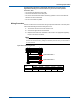
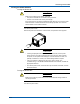
Wiring Procedure
Thereisaterminalcoverscrewedontothesignalinputterminalblockontherearpanel.
It has a label indicating the terminal arrangement on it.
1.
Turn the MV OFF and remove the terminal cover.
2.
Connect the signal wires to the terminals.
3.
Replace the terminal cover and fasten it with screws. The appropriate tightening
torque for the screws is 0.6N/m.
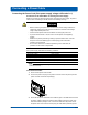
Note
It may be difficult to firmly secure input signal wires with diameters of 0.3 mm or less to clamp
terminals. To secure the wires, try folding the conductive parts over when you connect them to
the clamp terminal.
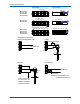
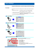
Input Terminal Arrangement
Input terminal block 2
Input terminal block 1
Input terminal
block
Channel allocation by model
MV1004 MV1006 MV1008 MV1012 MV1024
1 1 to 4 1 to 12
2 1 to 4 1 to 6 5 to 8 1 to 12 13 to 24
Connecting Input Cables
23
M-4661