User’s Manual RD-MV1000 First Step Guide M-4661 1st Edition
Contents Safety Precautions..............................................................................................................................................6 Handling Precautions of the MV.........................................................................................................................8 CF Card Handling Precautions...........................................................................................................................8 Protection of Environment..........
Contents RD-MV1000/RD-MV2000 User’s Manual (Electronic Manual Provided on the Accompanying CD) Chapter 1 Feature Overview Chapter 2 Installation and Wiring Chapter 3 Measurement Channels and Alarms Chapter 4 Measurement and Recording Chapter 5 Screen Operations Chapter 6 Display Configuration Chapter 7 Event Action Chapter 8 Security Functions Chapter 9 Environment Settings Chapter 10 Computation and Report Functions (/M1 and /PM1 Options) Chapter 11 External Input Channels (/MC1 Option) Chapter 12 Troubles
1st Edition: July 2008 All Rights Reserved, Copyright © 2008, Omega M-4661 5
Safety Precautions • This instrument conforms to IEC safety class I (provided with terminal for protective grounding), Installation Category II, and EN61326-1 (EMC standard), Measurement Category II (CAT II)*. * Measurement category II (CAT II) applies to measuring circuits connected to low voltage installation, and electrical instruments supplied with power from fixed equipment such as electric switchboards.
WARNING • Use the Correct Power Supply Ensure that the source voltage matches the voltage of the power supply before turning the power ON. • Use the Correct Power Cord and Plug To prevent electric shock or fire, be sure to use the power cord supplied by Omega. The main power plug must be plugged into an outlet with a protective ground terminal. Do not disable this protection by using an extension cord without protective grounding.
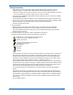
• Handling Precautions of the Software • Omega makes no warranties regarding the software accompanying this product except those stated in the WARRANTY that is provided separately. • Use the software on a single PC. • You must purchase another copy of the software, if you are to use the software on another PC. • Copying the software for any purposes other than backup is strictly prohibited.
Protection of Environment Control of Pollution Caused by the Product For details, see Control of Pollution Caused by the Product (IM RD-MV1000-91C). Proper Disposal of This Product This is an explanation of how to dispose of this product based on Waste Electrical and Electronic Equipment (WEEE), Directive 2002/96/EC. This directive is only valid in the EU. • Marking This product complies with the WEEE Directive (2002/96/EC) marking requirement.
Memo 10 M-4661
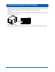
Checking the Contents of the Package Unpack the box and check the contents before operating the instrument. If some of the contents are not correct or missing or if there is physical damage, contact the dealer from which you purchased them. RD-MV1000 There is a name plate on the side panel of the MV. Check that the model name and suffix code given on the name plate match those on your order. MODEL STYLE H S SUFFIX SUPPLY FREQUENCY NO. NO.
Checking the Contents of the Package MODEL and SUFFIX Code Model code MV1004 MV1006 MV1008 MV1012 MV1024 Internal memory size External storage medium Language Input terminal Power supply Power cord Suffix code Description 4 channel, 125 ms (fast sampling mode: 25 ms) 6 channel, 1 s (fast sampling mode: 125 ms) 8 channel, 125 ms (fast sampling mode: 25 ms) 12 channel, 1 s (fast sampling mode: 125 ms) 24 channel, 1 s (fast sampling mode: 125 ms) Standard Memory Large Memory CF card (with medium) and USB -
Checking the Contents of the Package Standard Accessories The standard accessories below are supplied with the instrument. Check that all contents are present and undamaged. No.
How to Use This Manual Conventions Used in This Manual • This user’s manual assumes that the display language is set to English (language suffix code -2). • For information on setting the display language, see section 9.4, “Changing the Display Language” in the RDMV1000/RD-MV2000 User’s Manual (IM RD-MV1000-01E). Unit K stands for 1024. Example: 768 KB (file size) k stands for 1000. Markings The following safety notations are used in this manual.
Names of Parts Front With the cover open Carrying handle LCD Trend display and all other operation and configuration screens are displayed here. Power switch CF card access indicator Power indicator Glows red when the power is ON CF card eject button USB 1.1 port CF card slot Cover Rear Panel Ethernet port A 10Base-T port USB 1.
Basic Operation Panel Keys LCD screen START/STOP key Starts or stops memory sampling. Keys DISP/ENTER key Up arrow key Left arrow key Down arrow key ESC key Cancels an operation. USER key Executes the assigned operation. Soft keys Select menu items displayed at the bottom of the screen. HISTORY key • When using the history function: Switches to the history screen. • When using the favorite function: Switches between the operation screens that have been registered to it (max. 8).
Basic Operation Entering Values and Characters The character/number input window and DISP/ENTER key are used to set the date/time, set the display span of the input range, set tags, set message strings, enter passwords, etc.
Memo 18 M-4661
RD-MV1000 Workflow To set up the MV for quick use in the field, follow these steps: Install Connect Cables Turn ON Set Measurement Range Connect input/output wires and the power cord to the rear panel terminals. Connecting Input Cables: Page 22, Connecting a Power Cable: Page 26 Turn the power ON. Connecting a Power Cable: page 29 Select the measurement range, and configure the data save options from the Quick settings menu.
Installation Location Install the MV indoors in an environment that meets the following conditions: • Temperature of 0 to 40°C Install the MV in a location where the temperature is 0 to 40°C, and the humidity is 20 to 80% RH (5 to 40°C). Only use the MV when there is no condensation on it. Note Condensation may form when moving the MV from a low temperature/humidity environment to a high temperature/humidity environment, or when there is a sudden change in temperature.
Installation Installation Install the MV on a flat surface. Note You cannot put the MV in a stack. • Using the stand When using the stand, push it out until it locks into place.
Connecting Input Cables Wiring to the Signal Input Terminals WARNING • To prevent electric shock, make sure that the power source is turned OFF. CAUTION • Exposing the input and output signal cables connected to the MV to high tension may damage the cables and the MV terminals. Do not stretch the cables to their limit, and make sure that the terminals are not being pulled on. • To prevent fire, only use signal cables with a temperature rating of 70°C or above.
Connecting Input Cables Connecting the input wires in parallel with other devices can cause signal degradation, affecting all connected devices. If you have to make a parallel connection, then • Turn the burnout detection function OFF. • Ground the instruments to the same point. • Do not turn other instruments ON or OFF during operation. This can have adverse effects on the other instruments. • Do not connect RTDs in parallel.
Connecting Input Cables Screw Terminal Clamp Terminal CH4 CH2 CH3 CH1 MV1004 input terminal block MV1008 input terminal block 1 CH3 CH1 /b +/A –/B CH4 CH2 CH6 CH4 CH2 CH5 CH3 CH1 MV1006 input terminal block CH5 CH3 CH1 /b +/A –/B MV1012 input terminal block MV1024 input terminal block 1 CH12 CH10 CH8 CH6 CH4 CH2 CH11 CH9 CH7 CH5 CH3 CH1 /b +/A –/B CH6 CH4 CH2 CH11 CH9 CH7 CH5 CH3 CH1 /b +/A –/B /b +/A –/B /b +/A –/B CH12 CH10 CH8 CH6 CH4 CH2 Wiring Screw Terminals TC input DC voltage input
Connecting Input Cables Wiring Clamped Terminals Connect the wires. Remove the terminal block. Recommended length of stripped wire: 7 mm Connect the terminal block. Flat-blade screwdriver Recommended wire size 0.08 to 1.5 mm2 (AWG28 to 16) Hold both ends of the terminal block and pull straight. Input signal wire First, loosen the screw at the front using a flat-blade screwdriver. Insert the input signal wire into the slit on the left side of the terminal block, and fasten the screw at the front.
Connecting a Power Cable Connecting the Power Cord (if the power supply voltage suffix code is -1) Precautions to Be Taken While Connecting the Power Supply Make sure to follow the warnings below when connecting the power supply. To prevent electric shock and damage to the MV, observe the following warnings. WARNING • Before connecting the power cord, ensure that the source voltage matches the rated supply voltage of the MV and that it is within the maximum rated voltage range of the provided power cord.
Connecting a Power Cable Connecting the Power Cord (if the power supply voltage suffix code is -2) When Using an AC Adapter Precautions to Be Taken While Connecting the Power Supply Make sure to follow the warnings below when connecting the power supply. To prevent electric shock and damage to the MV, observe the following warnings. WARNING • To prevent electric shock, make sure that the power source is turned OFF. • Only use the power cord that Omega provides for use with the MV.
Connecting a Power Cable When Using a DC Power Supply Precautions to Be Taken While Connecting the Power Supply Make sure to follow the warnings below when connecting the power supply. To prevent electric shock and damage to the MV, observe the following warnings. WARNING • To prevent electric shock, make sure that the power source is turned OFF. • To prevent fire, use cables with a cross-sectional area of 0.5 mm2 (AWG20) or more.
Connecting a Power Cable Turning the Power ON/OFF Turning the Power ON CAUTION Before turning ON the power switch, check that • The power cord/wires are connected correctly to the MV. • The MV is connected to the correct power supply. If the input wires are connected in parallel with other devices, do not turn the power switch of the MV or another device ON or OFF during operation. This can have adverse effects on the measured values. Turn ON the power switch.
Quick Settings Using the quick settings function, you can switch quickly to the measurement channel (measurement range and alarm) and data save configuration screens by pressing T/DIV. Procedure Operate the MV from the Quick settings screen according to the procedure described below.
Quick Settings Press T/DIV Change the display-data save settings 1. Select the Trend/Storage interval. Press the 1min soft key. 2. Select the Save interval. Press the 1h soft key. Note This screen does not appear with the default settings. In A/D, Memory in Basic setting mode, set the data type to E+D Press T/DIV. Change the event data display settings. 1. Select the Sample rate. Press the 1s soft key. 2. Select the recording Mode. Press the Free soft key. 3. Select the Data length.
Measurement Inserting the CF Card 1. Open the cover. CAUTION is h T e id s p u “This side up” facing up CF card 2. Insert the CF card into the slot. The CF card icon is displayed. If the MV does not recognize the CF card, try reinserting it. 3. Close the cover. Check that the CF card slot eject button is depressed before closing the cover. Operation complete.
Measurement Starting the Memory Sample 1. Press START/STOP once. Memory sampling starts, and the key blinks green. START/STOP key Recording data Memory sampling progress DISP: Display data EVENT: Event data Operation complete. Stopping the Memory Sample 1. Press the START/STOP key when it is blinking green. Confirmation window 2. Select Mem+Math or Memory using the left and right arrow keys. Memory: Stops memory sampling. Mem+Math: Stops memory sampling and computation (option).
Measurement Removing the CF Card 1. Press FUNC once. 2. Press Media eject once. Displays the CF card icon 3. Press the CF soft key once. The message “Media can be removed safely” appears. The CF card icon is blue. 4. Open the cover. 5. Press the CF card eject button. When you eject the CF card, the storage media icon disappears. Push on the eject button until it clicks. The eject button remains depressed. Pinch the left and right sides of the CF card and remove it. Eject button 6.
Memo M-4661 35
Default RD-MV1000 Settings The setting mode and basic setting mode settings and their default values are listed in this section.
Default RD-MV1000 Settings • Menu Page 49 Page 50 Page 50 Page 501 Pages 50 and 511 Page 512 Page 51 Pages 52 to 55 Page 552 Page 55 Page 56 1 The function will be displayed if you choose to use it in Environment.
Default RD-MV1000 Settings Setting Mode Settings and Default Values Menu Tab Meas channel > Range, Alarm Setting First-CH, Last-CH Range > Mode Volt Range Selectable Range or Choices Numeric value (channel number) 1 to 24 Skip/Volt/TC/RTD/Scale/Delta/DI/1-5V/Sqrt Default Value 1 Volt 20mV/60mV/200mV/2V/6V/20V/50V 2V Span_L Span_U Numeric value (depends on the range) Numeric value (depends on the range) –2.0000 2.
Default RD-MV1000 Settings Setting Range > Alarm 1 to 4 Type Value Relay No. Detect Selectable Range or Choices On/Off H/L/h/l/R/r/T/t Numeric value On/Off I01 to I06, S01 to S30 On/Off Default Value Off H 0.
Default RD-MV1000 Settings Meas channel > Alarm mark Setting First-CH, Last-CH Mark kind Indicate on Scale Alarm mark color > Alarm 1 to 4 Selectable Range or Choices Numeric value (channel number) 1 to 24 Alarm/Fixed On/Off Red/Green/Blue/B.violet/Brown/Orange/Y.green/ Lightblue/Violet/Gray/Lime/Cyan/Darkblue/Yellow/ Lightgray/Purple/Black/Pink/L.brown/L.green/Darkgray/ Olieve/DarkCyan/S.
Default RD-MV1000 Settings Math channel > TLOG, Rolling average Setting First-CH, Last-CH TLOG Rolling average Selectable Range or Choices Numeric value (computation channel number) 101 to 124 Timer/MatchTimeTimer 1/2/3/4 Off, /s, /min, /h On/Off On/Off 1s/2s/3s/4s/5s/6s/10s/12s/15s/20s/30s/1min/2min/3m in/4min/5min/6min/10min/12min/15min/20min/30min/ 1h Numeric value (1 to 1500) Default Value 101 Selectable Range or Choices 101–106/107–112/113–118/119–124 Red/Green/Blue/B.violet/Brown/Orange/Y.
Default RD-MV1000 Settings Math channel > Color scale band Setting First-CH, Last-CH Band area Color Display position > Lower Display position > Upper Selectable Range or Choices Numeric value (computation channel number) 101 to 124 Off/In/Out Red/Green/Blue/B.violet/Brown/Orange/Y.green/ Lightblue/Violet/Gray/Lime/Cyan/Darkblue/ Yellow/Lightgray/Purple/Black/Pink/L.brown/ L.green/Darkgray/Olieve/DarkCyan/S.
Default RD-MV1000 Settings Display > Trend Setting Direction Trend clear Message direction Scale > Digit Scale > Value indicator Trend line Grid Second interval Selectable Range or Choices Horizontal/Vertical/Wide/Split On/Off Horizontal/Vertical Normal/Fine Mark/Bargraph 1/2/3 dot Auto/4/5/...
Default RD-MV1000 Settings Message Setting Message No. Characters Selectable Range or Choices 1–10/11–20/21–30/31–40/41–50/51–60/61–70/71–80/81– 90/91–100 Character string (up to 32 characters) Default Value 1–10 — Timer, Event action > Timer Setting Timer No. Mode Mode > Relative Interval Reset at Math Start Mode > Absolute Interval Ref.
Default RD-MV1000 Settings Timer, Event action > Event action Setting Logic box number Event Event > Remote Remote number Action Event > Relay Relay number Action Event > Switch Switch No. Action Event > Timer Timer No. Action Event > MatchTimeTimer Timer No. Action Event > Alarm Action Event > UserKey Action M-4661 Selectable Range or Choices 1/2/3/4/...
Default RD-MV1000 Settings Menu customize > Function menu Setting Pause Display Message Free message Media eject Snap shot Manual sample AlarmACK LCD Saver Trigger Save display Save event Save stop Math Start Math reset Math ACK Timer rest Match T Reset Keylock Logout Password change Second speed Batch Text field Favorite regist Standard display System info Network info SNTP E-Mail start E-Mail test FTP test Choices Select/Hide Menu customize > Display menu Setting ESC TREND TREND HISTORY DIGITAL BAR OV
Default RD-MV1000 Settings Setting INFORMATION LOG Sub Menu ALARM SUMMARY MESSAGE SUMMARY MEMORY SUMMARY MODBUS CLIENT MODBUS MASTER RELAY REPORT DATA COLUMN BAR TO HISTORY TO HISTORY(DISP) TO HISTORY(EV) TO OVERVIEW CHANGE SORT KEY ASCENDING/DESCENDING ORDER DATA SAVE MODE SELECT SAVE M.
Default RD-MV1000 Settings Basic Setting Mode Settings and Default Values Environment Tab Operating environment Setting Operating environment Tag/Channel Language Temperature Decimal Point Type Selectable Range or Choices Default Value Tag/Channel English/Japanese/German/French/Chinese/Korean C/F Point/Comma Tag English C Point Selectable Range or Choices Default Value T-Y On/Off On/Off T-Y Off Off Common/Separate On/Off On/Off Common Off Off Selectable Range or Choices Default Value Free/Over
Default RD-MV1000 Settings Communication > POP3 Details Setting POP3 Details Send delay [second] POP3 Login Selectable Range or Choices Default Value 0 to 10 s PLAIN/APOP 2 PLAIN Selectable Range or Choices Default Value +Over/-Over Error/Skip/Limit Over/Skip +Over Skip Over Selectable Range or Choices Default Value Max/Min/Ave/Sum/Inst Off/Max/Min/Ave/Sum/Inst Off/Max/Min/Ave/Sum/Inst Off/Max/Min/Ave/Sum/Inst Separate/Combine Ave Max Min Sum Separate Selectable Range or Choices Yes/No/Cancel
Default RD-MV1000 Settings A/D, Memory Setting Scan interval > Scan mode Normal > Scan interval Normal > A/D integrate Fast > Scan interval Fast > A/D integrate Memory Data kind Selectable Range or Choices Normal/Fast 125ms/250ms (MV1004, MV1008) 1s/2s/5s (MV1006, MV1012, MV1024) Auto/50Hz/60Hz 25ms (MV1004, MV1008) 125ms (MV1006, MV1012, MV1024) 600Hz Default Value Normal 125ms 1s Auto 25ms 125ms 600Hz Display/E+D/Event Event Selectable Range or Choices 1/2/3/…/23/24 (varies depending on the model) O
Default RD-MV1000 Settings Login > User settings Setting User number Mode User name Password Authority of user Selectable Range or Choices 1/2/3/…/29/30 Default Value 1 Off/Key/Comm/Web/Key+Comm Character string (up to 20 characters) Character string (up to 8 characters) Off/1/2/3/4/5/6/7/8/9/10 Off User1, etc.
Default RD-MV1000 Settings Communication (Ethernet) > IP-address Setting IP-address DHCP DNS accession Host-name register Fixed IP-address > IP-address Fixed IP-address > Subnet mask Fixed IP-address > Default gateway Selectable Range or Choices Default Value Use/Not Use/Not Use/Not Numeric value (0.0.0.0 to 255.255.255.255) Numeric value (0.0.0.0 to 255.255.255.255) Numeric value (0.0.0.0 to 255.255.255.255) Not Use Use 0.0.0.0 0.0.0.0 0.0.0.
Default RD-MV1000 Settings Communication (Ethernet) > E-Mail > Basic settings Setting Basic settings SMTP server name Port number Security Selectable Range or Choices Default Value Character string (up to 64 characters) Numeric value (0 to 65535) Off/PbS — 25 Off Communication (Ethernet) > E-Mail > Recipients Setting Recipients Recipient 1 Recipient 2 Sender Selectable Range or Choices Default Value Character string (up to 150 characters) Character string (up to 150 characters) Character string (up
Default RD-MV1000 Settings Communication (Ethernet) > E-Mail > System settings Setting System settings Recipient 1 Recipient 2 Include source URL Subject Header 1 Header 2 Selectable Range or Choices Default Value On/Off On/Off On/Off Character string (up to 32 characters) Character string (up to 64 characters) Character string (up to 64 characters) Off Off Off System_warning — — Communication (Ethernet) > E-Mail > Report settings Setting Report settings Recipient 1 Recipient 2 Include source URL Subj
Default RD-MV1000 Settings Communication (Ethernet) > Modbus client > Modbus server settings Setting Server number Port Modbus server name Unit No. Selectable Range or Choices 1-8/9-16 Numeric value (0 to 65535) Character string (up to 64 characters) Auto/Fixed 0 to 255 Default Value 1-8 502 — Auto 1 Communication (Ethernet) > Modbus client > Command settings Setting Master command number 1 to 16 First Last Server Regi.
Default RD-MV1000 Settings Status relay Setting Status relay Memory/Media status Measurement error Communication error Memory stop Selectable Range or Choices Default Value On/Off On/Off On/Off On/Off Off Off Off Off Selectable Range or Choices Yes/No/Cancel Default Value — Selectable Range or Choices Yes/No Default Value — Selectable Range or Choices Yes/No Default Value — End Setting Do you want to store and make the new settings take effect? Initialize Tab Clear settings and data Setting Are