
User guide
4-9
M-4662
Commands
1
2
3
4
5
6
7
App
Index
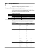
InputType InputType
Parameter
Range Range
Parameter
Required
Option
Cu53 CU53 /N3
RTD
RTD Cu100 /N3
Cu10:GE /N1
Cu10:L&N /N1
Cu10:WEED /N1
Cu10:BAILEY /N1
Cu10:0.000392at20 /N1
Cu10:0.000393at20 /N1
Cu25:0.00425at0 /N1
Pt25 /N3
Contact input
DI Level LEVEL
Cont CONT
1-5V voltage
1-5V 1-5V 1-5V
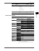
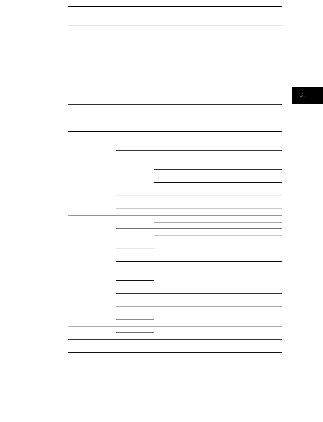
ChannelNumberNotations
The table below lists the channel notations that are used.
ChannelType Model ChannelNotation Notes
Measurement
channel
RD-MV1000 001 to 024 Varies depending on the
number of inputs
RD-MV2000 001 to 048 Varies depending on the
number of inputs
Computation
channel
RD-MV1000 101 to 112 High-speed input model
101 to 124 Medium-speed input model
RD-MV2000 101 to 112 High-speed input model
101 to 160 Medium-speed input model
External input
channel
RD-MV1000 --- Not available
RD-MV2000 201 to 440 with the /MC1 option
Manual sample RD-MV1000 --- Not available
RD-MV2000 001 to 120 with the /MC1 option
Report channel RD-MV1000 R01 to R12 High-speed input model
R01 to R24 Medium-speed input model
RD-MV2000 R01 to R12 High-speed input model
R01 to R60 Medium-speed input model
Internal switch RD-MV1000 S01 to S30
RD-MV2000
Output relay RD-MV1000 I01 to I06
RD-MV2000 I01 to I06, I11 to I16, I21
to I26, I31 to I36
Varies depending on the
options
Constant RD-MV1000 K01 to K60
RD-MV2000
Communication
input channel
RD-MV1000 C01 to C24
RD-MV2000 C01 to C60
Display group RD-MV1000 1 to 10
RD-MV2000 1 to 36
Remote control
terminal
RD-MV1000 D01 to D08
RD-MV2000
Pulse input RD-MV1000 P01 to P08,
Q01 to Q08
RD-MV2000
Flag RD-MV1000 F01 to F08
RD-MV2000
High-speed input model RD-MV1004, RD-MV1008, RD-MV2008
Medium-speed input model RD-MV1006, RD-MV1012, RD-MV1024
RD-MV2010, RD-MV2020, RD-MV2030, RD-MV2040, RD-MV2048
4.3 Setup Parameters