
User guide
4-8
M-4662
4.3 SetupParameters
The measurement range and setup range of parameters used in a command vary
depending on the combination of the command, range, and options.
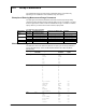
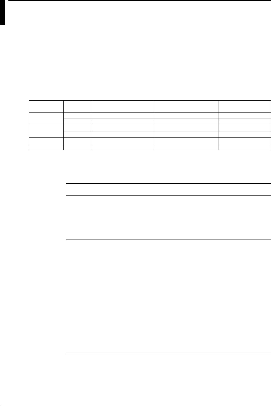
ExamplesofEnteringMeasurementRangeParameters
The span upper and lower limit parameters of the SR command (input range setting
command) requires all digits including fractional digits to be set. For example, if you want
to set the upper limit to 1.0000 V when the measurement range is –2.0000 V to 2.0000 V,
specify 10000. If you want to set the limit to 0.5000 V, specify 5000.
The table below gives examples.
Measurement
Range
InputType
Parameter
SelectableRangeof
MeasurementRange
TheRangeYouWanttoSet Parameter
VOLT 20mV
-20.000mV
to
20.000mV -10.000mV
to
20.000mV -10000
to
20000
/SQRT 2V
-2.0000V
to
2.0000V -2.0000V
to
0.5000V -20000
to
5000
TC R
0.0
to
1760.0 0.0
to
400.0 0
to
4000
K
-200.0
to
1370.0 -200.0
to
1370.0 -2000
to
13700
RTD Pt100
-200.0
to
600.0 -10.0
to
500.0 -100
to
5000
DI LEVEL
0
to
1 0
to
1 0
to
1
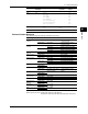
MeasurementRangeParameters
The table below shows the relationship between the input types and range parameters.
For the selectable range, see the RD-MV1000/RD-MV2000 User’s Manual (IM RD-
MV1000-01E).
InputType InputType
Parameter
Range Range
Parameter
Required
Option
DC voltage
VOLT 20mV 20MV
60mV 60MV
200mV 200MV
2V 2V
6V 6V
20V 20V
50V 50V
Thermocouple
TC R R
S S
B B
K K
E E
J J
T T
N N
W W
L L
U U
Kp vs Au7Fe KP /N3
PLATINEL PLATI /N3
PR40-20 PR /N3
NiNiMo NIMO /N3
WRe WRE
W/WRe26 W/WRE /N3
TypeN(AWG14) N2 /N3
RTD
RTD Pt PT
JPt JPT
Pt50 PT50 /N3
Ni100(SAMA) NI1 /N3
Ni100(DIN) NI2 /N3
Ni120 NI3 /N3
J263*B J263 /N3