
User guide
3-11
M-4662
UsingtheSerialInterface
1
2
3
4
5
6
7
App
Index
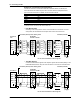
• First/Last(MVchannelnumbers)
Enter the first and last channel numbers of input/output. The range of channels that
you can enter varies depending on the command type as follows:
R: 201 to 440, R-M: C01 to C60, W: 1 to 48, W-M: 101 to 160
• Address
Enter the slave device address in the range of 1 to 247.
• Regi.
Set the slave register number.
Enter an input register in the range of 30001 to 39999 and 300001 to 365536 or a hold
register in the range of 40001 to 49999 and 400001 to 465536.
The register numbers that you can specify vary depending on the command type. See
section 7.3 for details.
• Type
The data type.
Select INT16, UINT16, INT32_B, INT32_L, UINT32_B, UINT32_L, FLOAT_B, or
FLOAT_L.
The data type that you can specify vary depending on the command type. See section
7.3 for details.
ExampleofEnteringCommands
See section 2.9.
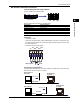
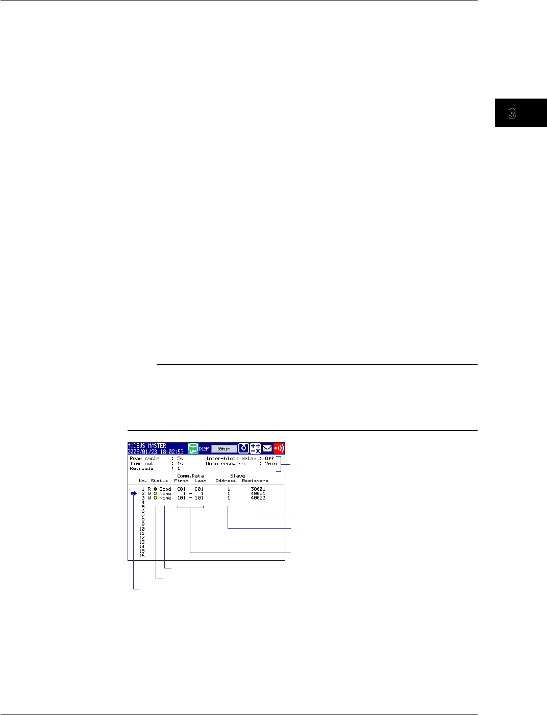
CheckingtheModbusOperatingStatus
DisplayingtheModbusOperatingStatus
◊ Press DISP/ENTER and then select INFORMATION > MODBUSMASTER
Note
To display the MODBUS MASTER on the display selection menu, you need to change the
setting using the menu customize feature. Carry out the following steps.
◊ Press MENU and then select Menu tab > Menucustomize > Displaymenu
1. Select INFORMATION > MODBUSMASTER using the arrow keys.
2. Press the View soft key.
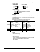
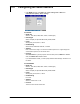
Slave device addresses
Register numbers
MV channels
Detail code
Status lamp
Cursor used to select a command
(Used to resume command transmission from the front panel keys)
Communication conditions
3.5 Reading/Writing Data on Another Device from the MV via Modbus