
User guide
3-6
M-4662
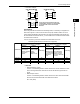
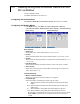
ExampleofaConnectiontotheHostDevice
The MV can connect to a host device that has an RS-232, RS422, or RS-485 port.
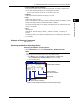
If the host device has an RS-232 port, use a converter. See the examples below for
typical converter terminals. For details, see the converter manual.
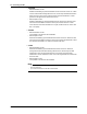
RS-422/485Port Converter
SDA(–) TD(–)
SDB(+) TD(+)
RDA(–) RD(–)
RDB(+) RD(+)
SG SHIELD
FG EARTH
There is no problem with connecting a 220-Ω terminator at each end if Omega PLCs or temperature
controllers are also connected in the communication line.
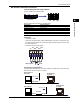
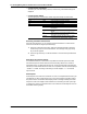
• Four-WireSystem
Generally, a four-wire system is used to connect the MV to a host device. In a four-
wire system, the transmission and reception lines need to be crossed over.
Terminator (external) 120 Ω 1/2W or greater
#1
Do not connect terminators to #1 through #n-1.
RS-422/485
terminal on the MV
#2 #n
(#n 32)
Terminator (external)
Host device
side
SG
RDB( + )
RDA( - )
SDB( + )
SDA( - )
FG
SG
RD B
RD A
SD B
SD A
(SG)
(RD B)
(RD A)
(SDB)
(SDA)
FG
SG
RD B
RD A
SD B
SD A
(SG)
(RD B)
(RD A)
(SDB)
(SDA)
FG
SG
RD B
RD A
SD B
SD A
(SG)
(RD B)
(RD A)
(SDB)
(SDA)
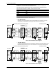
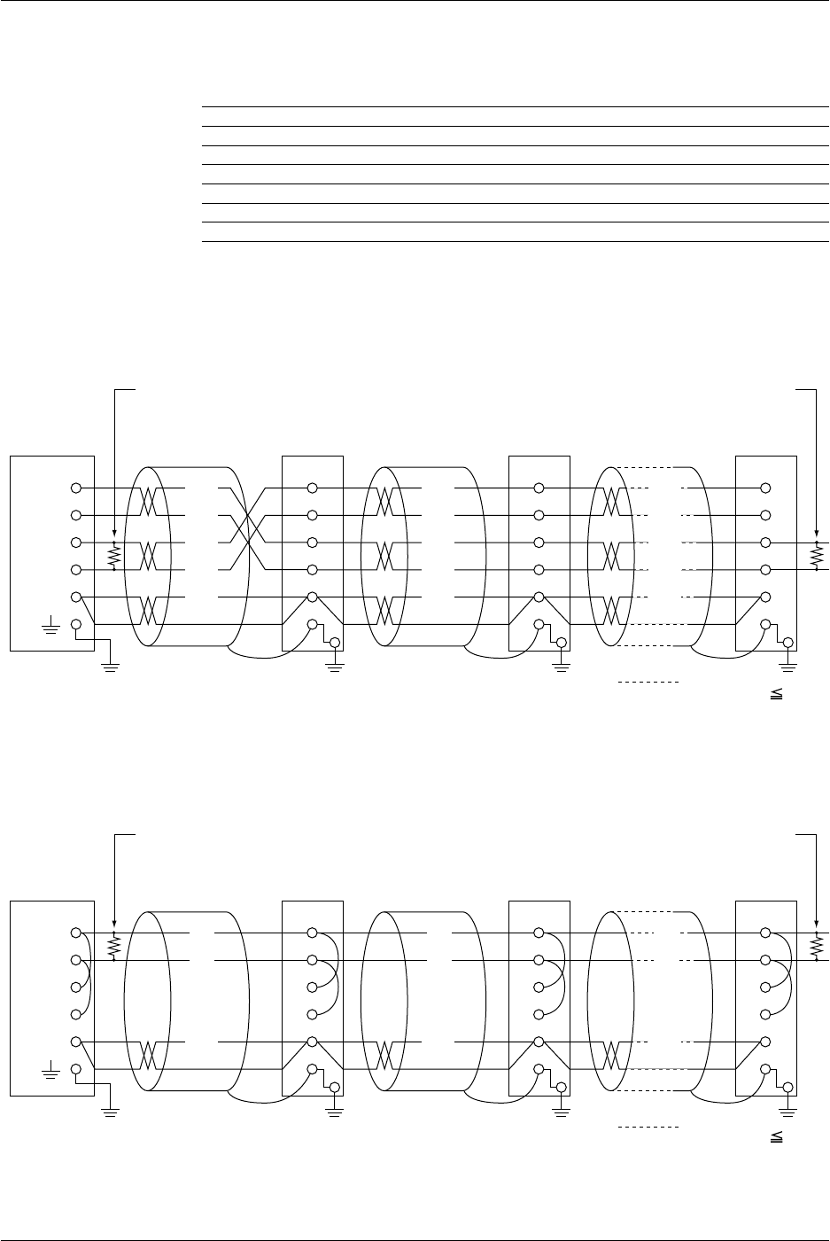
• Two-WireSystem
Connect the transmission signals to the reception signals with the same polarity on the
RS422/485 terminal block. Only two wires are used to connect to the external device.
Terminator (external) 120 Ω 1/2W or greater
#1
Do not connect terminators to #1 through #n-1.
RS-422/485
terminal on the MV
#2 #n
(#n 31)
Terminator (external)
Host device
SG
RDB( + )
RDA( - )
SDB( + )
SDA( - )
FG
SG
RD B
RD A
SD B
SD A
(SG)
(B)
(A)
(B)
(A)
FG
SG
RD B
RD A
SD B
SD A
(SG)
FG
SG
RD B
RD A
SD B
SD A
(SG)
(B)
(A)
3.2ConnectingtheMV