
User guide
3-2
M-4662
3.2 ConnectingtheMV
ConnectingaCable
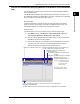
Connect a cable to the serial port on the MV rear panel.
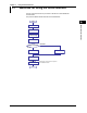
RS-232ConnectionProcedure
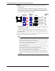
Connect a cable to the 9-pin D-sub RS-232 connector.
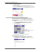
ConnectorPinArrangementandSignalNames
1 2 3 4 5
6 7 8 9
(Rear panel)
Pin assignments are shown in the table below.
The table shows the signal names as defined by the RS-232 , JIS, and ITU-T
standards along with their description.
Pin SignalName Name SignalDescription
JIS ITU-T RS-232
2 RD 104 BB(RXD) Received data Input signal to the MV.
3 SD 103 BA(TXD) Transmitted
data
Output signal from the MV.
5 SG 102 AB(GND) Signal ground Signal ground.
7 RS 105 CA(RTS) Request to
send
Handshaking signal transmitted
from the MV used to receive data
from the PC.
8 CS 106 CB(CTS) Clear to send Handshaking signal transmitted
from the MV used to receive data
from the PC.
* Pins 1, 4, 6, and 9 are not used.
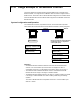
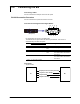
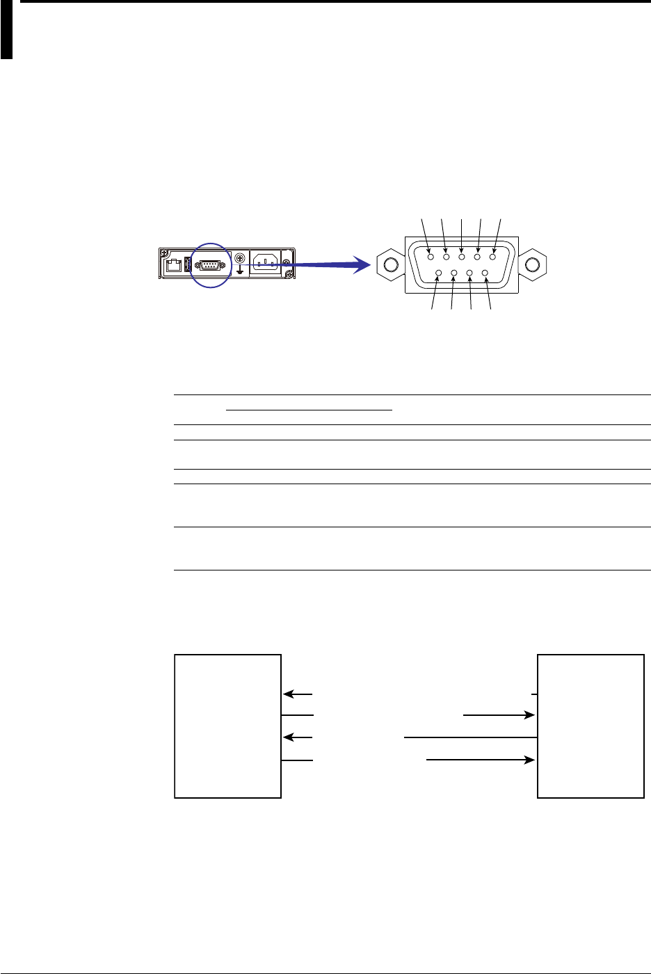
Connection
• Signal direction
PC MV
RS [Request to send...Ready to receive]
SD [Send data]
RD [Received data]
2
3
8
7
CS [Clear to send...Ready]