
Manual


2-9
M-4660
Installation and Wiring
1
2
3
4
5
6
7
8
9
10
11
12
13
App
Index
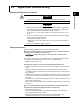
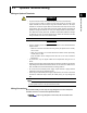
Optional Terminal Block Assignment
1 to 8: Remote control
terminal numbers
C: Common
NC: Normally closed
C: Common
NO: Normally opened
NC
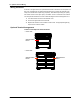
Remote
Alarm, FAIL, status output
H, L: See “Pulse Input
Terminals (/PM1)”
in this chapter.
Pulse input
+ , –: See “24VDC Transmitter
Power Supply Output
Terminal (/TPS2, /TPS4)”
in this chapter.
Transmitter power supply output
Letters such as NC: Indicate the terminal's functions.
Unused terminal (screws included).
Unused terminal (no screws included).
Symbols
02 0104 03
NC
C
NO
NC
C
NO
NC
C
NO
NC
C
NO
NC
C
NO
NC
C
NO
NC
C
NO
NC
C
NO
NC
C
NO
NC
C
NO
NC
C
NO
NC
C
NO
NC
C
NO
NC
C
NO
NC
C
NO
NC
C
NO
NC
C
NO
NC
C
NO
NC
C
NO
NC
C
NO
NC
C
NO
NC
C
NO
NC
C
NO
NC
C
NO
NC
C
NO
NC
C
NO
NC
C
NO
NC
C
NO
NC
C
NO
NC
C
NO
NC
C
NO
NC
C
NO
02 01
02 0104 0306 05
C
1
2
8
7
6
5
4
3
C
1
2
8
7
6
5
4
3
C
1
2
8
7
6
5
4
3
02 0104 0306 05
02 01
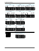
Remote
Remote
Remote
C
1
2
8
7
6
5
4
3
Remote
Alarm
Alarm
NC
C
NO
NC
C
NO
02 01
Alarm
Alarm
02 0104 03
Alarm
02 0104 03
Alarm
Alarm
02 0104 0306 05
Alarm
FAIL
Status output
FAIL
Status output
/A1 /A2 /A3
/A1/R1 /A2/R1 /A3/R1
/R1 /A1/F1 /A2/F1
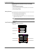
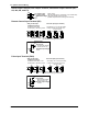
Options that only use terminal block 1
1
1
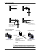
2.3 Optional Terminal Wiring