
Manual

11-2
M-4660
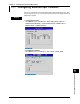
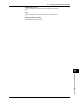
• Tag,Memorysample,andAlarmdelay
Press MENU and then select Menu tab > Ext. channel > Tag, Memory sample, Alarm
delay.
• ChannelstoBeManuallySampled
See section 4.5.
Settings
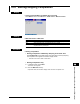
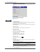
• ConfiguringtheInput
The measured values of external devices are loaded into external input channels by
using the Modbus client or Modbus master function.
For conguration instructions, see the Communication Interface User’s Manual (IM
RD-MV1000-17E).
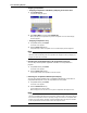
• First-CH,Last-CH
Select the target channels. Channel numbers are from 201 to 440.
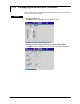
• Ext.range>On/Off
Select On to use the channels.
• Ext.range>SpanLower,SpanUpper
The measurement range.
Selectable range of values: –30000 to 30000
Decimal place: Up to four fractional digits
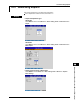
• Ext.range>Unit
Set the unit (up to six characters,
A
a
#
1
).
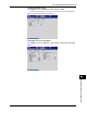
• Ext.alarm
The available alarm types are high limit alarm, low limit alarm, delay high limit alarm,
and delay low limit alarm.
The range of alarm values is as follows:
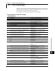
Type Alarm Values Example of Alarm Values
H, L In the range of –30000 to 30000 ignoring
the decimal point
If the span is 0.0 to 100.0:
–3000.0 to 3000.0
T, t Same as H, L Same as H, L
For alarm conguration instructions, see section 3.7.
* If you change the On/Off or span settings of an external input channel, the alarm on that
channel will be set to Off.
11.1 Configuring External Input Channels