
User Manual


IM 01E20C02-01E
6-27
6. PARAMETER DESCRIPTION
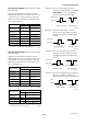
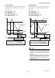
Output Example 2
The high alarm (H) is set to 80% or more of the flow
rate span; the low-low alarm (LL), to 20% or less.
Settings are:
G10: Low Alarm = -110%
G11: High Alarm = 80%
G12: Low Low Alarm = 20%
G13: High High Alarm = 110%
0 Time (t)
H
DO
DIO
LL
Instantaneous flow rate
20
50
80
100
[%]
Select “H/L Alarm(O)” for F20: DO Function
Select “HH/LL Alarm(O)” for F21: DIO Function
Select “Closed (On) Act” for F22: DO Active Mode
Select “Closed/Short Act” for F23: DIO Active Mode
F0609.EPS
L Alarm set to
-110% indicates
that the alarm is
disabled.
HH Alarm set to 110% indicates
that the alarm is disabled.
High Alarm
Low Low Alarm
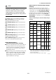
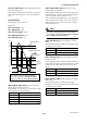
Output Example 3
The high alarm (H) is set to 80% or more of the flow
rate span; the high-high alarm (HH), to 90% or more.
Settings are:
G10: Low Alarm = -110%
G11: High Alarm = 80%
G12: Low Low Alarm = -110%
G13: High High Alarm = 90%
0 Time (t)
H
HH
DO
DIO
Instantaneous flow rate
50
80
90
100
[%]
F0610.EPS
High High Alarm
High Alarm
Select “H/L Alarm(O)” for F20: DO Function
Select “HH/LL Alarm(O)” for F21: DIO Function
Select “Closed (On) Act” for F22: DO Active Mode
Select “Closed/Short Act” for F23: DIO Active Mode
L Alarm set to
-110% indicates
that the alarm is
disabled.
LL Alarm set to -110% indicates
that the alarm is disabled.
NOTE
• Although the same items can be selected using
the DO terminal (selected for F20) and the DIO
terminal (selected for F21), output is identical
for both.
• Setting values of -110% and 110% are used to
disable corresponding functions; and accord-
ingly, status output can be customized for
specific purposes.