
User Manual


IM 01E20C02-01E
4-4
4. WIRING
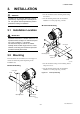
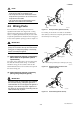
(3) Conduit Wiring
When wiring the conduits, pass the conduit through the
wiring connection port, and utilize the waterproof
gland to prevent water from flowing in. Place the
conduit pipe on an angle as shown in Figure 4.3.4.
Install a drain valve at the low end of the vertical pipe,
and open the valve regularly.
Drain valve
F0407.EPS
Figure 4.3.4 Conduit Wiring
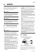
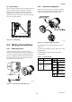
4.4 Wiring Connections
4.4.1 Removing Cover
Loosen cover locking screw 2 clockwise using a
hexagonal wrench (nominal size 3 mm) to unlock the
cover. (Upon shipment from the manufacturing plant,
the cover is unlocked.) Hold the flowmeter with your
hand and remove the cover by turning it in the direc-
tion of the arrow as shown below.
F0408.EPS
Cover locking screws
Figure 4.4.1 Removing the Terminal Box Cover
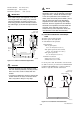
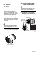
4.4.2 Terminal Configuration
When the cover is removed, the connection terminals
will be visible. The terminal configuration labels are
attached in the locations shown in Figure 4.4.2.
F0409.EPS
Figure 4.4.2 Terminal Layout Labels Position
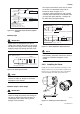
The description of the terminal symbols is shown in
Table 4.1.1.
For FOUNDATION Fieldbus protocol, please refer to IM
01E20F02-01E.
For PROFIBUS PA protocol, please refer to IM
01E20F12-01E.
Table 4.1.1 Terminal Symbols
T0401.EPS
Flow singal
input
Excitation current
output
Power supply
Current output
4 to 20mA DC
Pulse output/
Alarm output/
Status output
Alarm output/
Status output/
Status input
Functional grounding
Ter minal
Symbols
Description
EX1
EX2
C
SA
A
B
SB
Ter minal
Symbols
Description
N/–
L/+
I+
I–
DO+
DO–
DIO+
DIO–
Protective grounding
(Outside of the terminal)