
User Manual


IM 01E20C02-01E
11-1
11. OUTLINE
■ STANDARD SPECIFICATIONS
Refer to IM 01E20F02-01E for FOUNDATION Fieldbus
communication type and IM 01E20F12-01E for
PROFIBUS PA communication type marked with “”
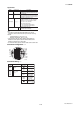
Converter
*1: Select two points from: one pulse output, one alarm
output, one status input, or two status outputs.
*2: For models without an indicator, the hand-held
terminal is necessary to set parameters.
Excitation Method: (Combined with AXF Remote
Flowtube)
• Standard dual frequency excitation:
Size 2.5 to 400 mm (0.1 to 16 in.)
• Enhanced dual frequency excitation:
Size 25 to 200 mm (1.0 to 8.0 in.)
(Optional code HF1 or HF2)
Input Signal (*1) “”:
One Status Input: Dry contact
Load resistance: 200 Ω or less (ON), 100 kΩ or more
(OFF)
Output Signals “”:
• One Current Output: 4 to 20 mA DC (load resistance:
750 Ω maximum, including cable resistance)
• One Pulse Output (*1):
Transistor contact output (open collector)
Contact capacity: 30 V DC (OFF), 200 mA (ON)
Output rate: 0.0001 to 10,000 pps (pulse/second)
• One Alarm Output (*1):
Transistor contact output (open collector)
Contact capacity: 30 V DC (OFF), 200 mA (ON)
• Two Status Outputs (*1):
Transistor contact output (open collector)
Contact capacity: 30 V DC (OFF), 200 mA (ON)
Communication Signals “”:
BRAIN or HART communication signal
(Superimposed on the 4 to 20 mA DC signal)
Distance from power line: 15 cm (6 in.) or more (Parallel
wiring should be avoided.)
BRAIN:
Communication Distance:
Up to 1.5 km (0.93 miles), when polyethylene insulated
PVC-sheathed cables (CEV cables) are used.
Communication distance varies depending on the type
of cable and wiring used.
Load Resistance:
250 to 450 Ω (including cable resistance)
Load Capacitance: 0.22 µF or less
Load Inductance: 3.3 mH or less
Input Impedance of Communicating Device:
10 kΩ or more (at 2.4 kHz)
11. OUTLINE
HART:
Load Resistance:
250 to 600 Ω (including cable resistance)
Note: HART is a registered trademark of the HART
Communication Foundation.
Data Security During Power Failure:
Data (parameters, totalizer value, etc.) storage by
EEPROM. No back-up battery required.
Indicator (*2):
Full dot-matrix LCD (32132 pixels)
Lightning Protector “”:
The lightning protector is built into the excitation current
output, the current output, the signal common, pulse/
alarm/status input and output terminals. When optional
code A is selected, the lightning protector is built into the
power terminals.
Protection:
General-purpose Use/Sanitary Type/TIIS Flameproof
type: IP66, IP67
Explosion proof type except TIIS:
In case of explosion proof type except TIIS, refer to
description of “Enclosure” in “HAZARDOUS AREA
CLASSIFICATION”.
Coating:
Case and Cover: Corrosion-resistant coating
Coating Color; Mint green (Munsell 5.6 BG 3.3/2.9 or its
equivalent)
Converter Material:
Case and Cover: Aluminum alloy
Mounting/Shapes:
• Mounting: 2-inch pipe
• Electrical Connection: ANSI 1/2 NPT female
ISO M20 1.5 female
JIS G1/2 (PF1/2) female
• Terminal Connection: M4 size screw terminal
Grounding:
Grounding resistance 100 Ω or less
When optional code A is selected, grounding resistance
10 Ω or less shall be applied.
* In case of explosion proof type except TIIS, follow the
domestic electrical requirements as regulated in each
country.
* In case of TIIS Flameproof type, refer to description of
“HAZARDOUS AREA CLASSIFICATION”.
Combined Remote Flowtube:
• AXFA14 Converter can be combined with size 2.5 to 400
mm (0.1 to 16 in.) of AXF Remote Flowtube.
• If a combined converter is changed from AXFA14 to
AXFA11 or vice versa, a new meter factor must be
adjusted by flow calibrations.
• In case that size 250 mm (10 in.) or larger is used in low
conductivity or high concentration slurries, please use the
AXFA11 Converter.