
User Manual


IM 01E20F12-01E
9-12
9. PARAMETER LISTS
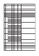
9.5 DI Block Parameter List (DI1: Slot5, DI2: Slot6)
T0905-1.EPS
Index Parameter Valid Range Initial Value Description
Write
Mode
16 BLOCK_OBJECT
(DS-32)
Information on this block such as Block Tag, DD Revision, Execution
Time etc.
–
17 ST_REV The revision level of the static data associated with the function
block. The revision value will be incremented each time a static
parameter value in the block is changed.
–0
18 TAG_DESC The user description of the intended application of the block.Auto Space
19 STRATEGY The strategy field can be used to identify grouping of blocks.
This data is not checked or processed by the block.
Auto 0 to 65535 0
20 ALERT_KEY The identification number of the plant unit. This information may be
used in the host for sorting alarms, etc.
Auto 0 to 255 0
21 TARGET_MODE Set the Target of block mode (MODE_BLK) to Auto, Man or O/S
according to the Write Mode of the parameter to be set or changed.
Auto The permitted bit is
only available.
Auto
30 CHANNEL Reference to the active Transducer Block which provides the
measurement value to the Function Block.
318: LIMSW_1_VALUE_D
324: LIMSW_2_VALUE_D
330: SWITCH_1_VALUE_D
332: SWITCH_2_VALUE_D
O/S 318, 324, 330, 332 DI1: 0x013E
(1, 62),
DI2: 0x0144
(1,68)
31 INVERT Indicates whether the input value of the PV_D should be logically
inverted before it is stored in the OUT_D.
Auto 0: not inverted
1: invert
0: not inverted
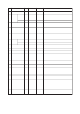
36 FSAFE_TYPE Defines reaction of device, if a fault is detected.Auto 0: FSAFE_VAL,
1: last valid OUT
Value
2: wrong calculated
Val
1: last valid
OUT Value
37 FSAFE_VAL_D Default value for the OUT_D parameter, if sensor or sensor
electronic fault is detected.
Auto 00 or 1
0: Disabled,
Enable exclude 0
40 SIMULATE
(DS-51)
41-50 reserved by PNO
51 VIEW_DI_FB View objects allow the following groups of physical block parameter
values to be read with one read request.
ST_REV, MODE_BLK, ALARM_SUM, OUT_D
–
For commissioning and test purposes the input value from the
Transducer Block in the Discrete Input Function Block, DI-FB can be
modified when the hardware simulation jumper is on. That means
that the Transducer and DI-FB will be disconnected.
Auto 0
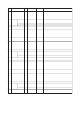
22 MODE_
BLK
(DS-37)
The mode parameter is a structured parameter composed of the
actual mode, the normal mode and the permitted mode.
Actual: Indicates the current operating condition.
Permit: Indicates the operating condition that the block is allowed
to take.
Normal: Indicates the operating condition that the block will
usually take.
–Auto
23 ALARM_
SUM
(DS-42)
Current The current alert status, unacknowledged status, unreported status
and disabled status of the alarms associated with the function block.
–Bit0, Bit7 are
available.
0
Value
This parameter contains the current measurement value from
Transducer Block or configuration adjusted engineering unit and the
belonging state in AUTO MODE.
OUT contains the value and status set by an operator in MAN MODE.
Man 0
Simulate_Status
Auto 0Simulate_Value
Auto 0: DisabledSimulate_Value
Actual
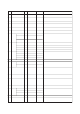
24 BATCH
(DS-67)
25 Not used
26 OUT_D
(DS-34)
This parameter is intended to be used in Batch applications in line
with IEC 61512 .
Auto 0
BATCH_ID
Auto 0
RUP
Man 0
Status
Auto 0
OPERATION
Auto 0
PHASE
–
O/S bit, Man bit,
Auto bit
O/S,Man,Auto
Permitted
–0for future use
Unacknowledged
–0for future useUnreported
–0for future use
Disabled
–The permitted bit is
only available.
Auto
Normal