
User Manual


IM 01E20F12-01E
9-11
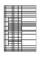
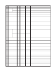
9. PARAMETER LISTS
T0904-2.EPS
Index Parameter Valid Range Initial Value Description
Write
Mode
32 PRESET_TOT This parameter is used in order to define the starting value to the
totalizer.
Auto -99999999 to
+99999999
0 or larger
0.000
33 ALARM_HYS Amount the PV must return within the alarm limits before the alarm
condition clears. Alarm Hysteresis is expressed as a percent of the
PV span.
Auto 0.000
34 HI_HI_LIM The setting for high high alarm in engineering units.
The setting for high alarm in engineering units.
The setting of the low alarm in engineering units.
The setting of the low low alarm in engineering units.
Auto max. Value +INF
35 HI_LIM Auto max. Value +INF
36 LO_LIM Auto min. Value -INF
37 LO_LO_LIM Auto min. Value -INF
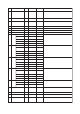
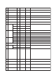
This parameter is used in order to set the state of the upper limit of
alarms.
This parameter contains the state of the upper limit of an alarm and
the related time stamp. The time stamp expresses the time the
measured variable has been equal or higher than the upper limit of
the alarm.
38 HI_HI_ALM
(DS-39)
–0Unacknow-
ledged
–0
Alarm State 0: No alarm
Alarm active
exclude 0
–0
Time_Stamp
–0
Subcode
–0
Value
This parameter is used in order to set the state of the upper limit of
warnings.
This parameter contains the state of the upper limit of a warning and
the related time stamp. The time stamp expresses the time the
measured variable has been equal or higher than the upper limit of
the warning.
39 HI_ALM
(DS-39)
–0Unacknow-
ledged
–0
Alarm State 0: No alarm
Alarm active
exclude 0
–0
Time_Stamp
–0
Subcode
–0
Value
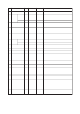
This parameter is used in order to set the state of the lower limit of
warnings.
This parameter contains the state of the lower limit of a warning and
the related time stamp. The time stamp expresses the time at which
the measured variable has been equal to or lower than the lower
limit of the warning.
40 LO_ALM
(DS-39)
–0Unacknow-
ledged
–0
Alarm State 0: No alarm
Alarm active
exclude 0
–0
Time_Stamp
–0
Subcode
–0
Value
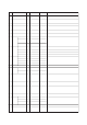
This parameter is used in order to set the state of the lower limit of
alarms.
This parameter contains the state of the lower limit of an alarm and
the related time stamp. The time stamp expresses the time at which
the measured variable has been equal to or lower than the lower
limit of the alarm.
41 LO_LO_ALM
(DS-39)
–0Unacknow-
ledged
–0
Alarm State 0:No alarm
Alarm active
exclude 0
–0
Time_Stamp
–0
Subcode
–0
Value
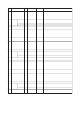
For commissioning and test purposes the input value from the
Transducer Block in the Totalizer Function Block, TOT-FB can be
modified when the hardware simulation jumper is on. That means
that the Transducer and TOT-FB will be disconnected.
52 SIMULATE
(DS-50)
42-51 reserved by PNO
0Simulate_
Status
Auto
View objects allow the following groups of physical block parameter
values to be read with one read request.
ST_REV, MODE_BLK, ALARM_SUM, TOTAL
53 VIEW_TOTALIZER_FB –
Auto 0
Simulate_
Value
Auto
0: Disabled,
Enable exclude 0
0: Disabled
Simulate_
Enabled