
User Manual


IM 01E20F12-01E
9-8
9. PARAMETER LISTS
T0903-4.EPS
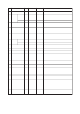
Index Parameter Valid Range Initial Value Description
Write
Mode
92 SWITCH_2_
VALUE_D
(DS-34)
Indicate the value of switch 2, which switches ON and OFF
depending on the digital value of the target input parameter selected
in SWITCH_2_TARGET.
–00: not set,
set exclude 0
93 SWITCH_2_TARGET This parameter selects the input channel used to LIMSW_2_
VALUE_D.
O/S 1: Adhesion
Warning
0: Adheshion Alarm
1: Adhesion Warning
94 SIGNAL_LOCK This parameter executes the signal lock function: If “Lock” is
selected, this function will be started.
Auto 0: Unlock
0: Unlock
1: Lock
95 ALARM_PERFORM This parameter masks Alarm/Warning. By setting “0” to each bit,
corresponding Alarm/Warning are cleared. When masked the
corresponding bit of DEVICE_STATUS becomes OFF and no alarm
is displayed on LCD, and also becomes out of scope of Primary
value status, ED_ERROR setting. Valid range is 0x00000000 to
0x003F003F.
O/S 0x00010033
0x00000000 to
0x003F003F
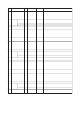
96 SIMULATE_MODE For commissioning and test purposes the input value from sensor
value in the Transducer Block. TB can be modified when the
hardware simulation jumper is on. It means that the sensor value
and TB will be disconnected.
Auto 0: Off
0: Off
1: Volume Flow
97 SIMULATE_TYPE Select the type of the simulated value.Auto 0: Fixed
0: Fixed
1: 2 points
2: 3 points
3: Ramp
98 SIMULATE_
VOLUME_
FLOW
(DS-33)
Set the fixed value for simulating the volume flow value when
SIMULATE_TYPE is selected “0: Fixed”.
When SIMULATE_MODE is selected “0: Off”, SIMULATE_
VOLUME_FLOW.Value has the same value as the current value
from the sensor. (That is, the sensor value is copied to this
parameter internally at each TB execution.) And SIMULATE_
VOLUME_FLOW.Status has the same value as VOLUME_FLOW_
VALUE.Status.
When SIMULATE_TYPE is not selected “0: Fixed”, SIMULATE_
VOLUME_FLOW shows the current simulated value.
Auto 0
Value
–Good
Status
Auto Good
Status
Value
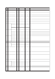
99 SIMULATE_UP_VALUE Set the simulated upper value when SIMULATE_TYPE is selected
“1: 2 points”, “2: 3 points”, or “Ramp”.
Auto 0Except
SIMULATE_LO_
VALUE
100 SIMULATE_LO_VALUE Set the simulated lower value when SIMULATE_TYPE is selected
“1: 2 points”, “2: 3 points”, or “3: Ramp”.
Auto 0Except
SIMULATE_UP_
VALUE
101 SIMULATE_TIME Show the time to maintain a constant value when SIMULATE_TYPE
is selected “1: 2 points” or “2: 3 points”.
Show the time to maintain a constant change, when SIMULATE_
TYPE is selected “3: Ramp”.
Auto 30Except 0
102 OPERATION_TIME This parameter is used to display the operation time. For example,
“1D23:45” indicates an operation time of 1 day, 23 hours, and 45
minutes.
–0D 00:000D 00:00 to
99999D 23:59
103 ALM_RECORD1 This parameter is used to display the most-recent alarm.–00 to 14
104 ALM_RECORD_TIME1 This parameter is used to display the operation time at which the
alarm indicated by Alm_Record1 was occurred. For example,
“1D23:45” indicates that an alarm was triggered at the operation
time of 1 day, 23 hours, and 45 minutes.
–0D 00:000D 00:00 to
99999D 23:59
105 ALM_RECORD2 This parameter is used to display the second most recent alarm.–00 to 14
106 ALM_RECORD_TIME2 This parameter is used to display the operation time at which the
alarm indicated by Alm_Record2 was occurred.
–0D 00:000D 00:00 to
99999D 23:59
107 ALM_RECORD3 This parameter is used to display the third most recent alarm.–00 to 14
108 ALM_RECORD_TIME3 This parameter is used to display the operation time at which the
alarm indicated by Alm_Record3 was occurred.
–0D 00:000D 00:00 to
99999D 23:59
109 ALM_RECORD4 This parameter is used to display the fourth most recent alarm.–00 to 14
110 ALM_RECORD_TIME4 This parameter is used to display the operation time at which the
alarm indicated by Alm_Record4 was occurred.
–0D 00:000D 00:00 to
99999D 23:59