
User Manual


IM 01E20F12-01E
9-5
9. PARAMETER LISTS
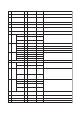
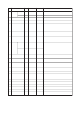
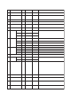
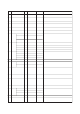
9.3 Transducer Block Parameter List (Slot 7)
T0903-1.EPS
Index Parameter Valid Range Initial Value Description
Write
Mode
16 BLOCK_OBJECT
(DS-32)
Information on this block such as Block Tag, DD Revision, Execution
Time etc.
17 ST_REV – 0 The revision level of the static data associated with the function
block. The revision value will be incremented each time a static
parameter value in the block is changed.
18 TAG_DESC Auto The user description of the intended application of the block.
19 STRATEGY Auto 0 to 65535 0
The strategy field can be used to identify grouping of blocks.
This data is not checked or processed by the block.
20 ALERT_KEY Auto 0 to 255 0
The identification number of the plant unit. This information may be
used in the host for sorting alarms, etc.
21 TARGET_MODE Auto The permitted bit is
only available.
0x08: Auto Set the Target of block mode (MODE_BLK) to Auto or O/S according
to the Write Mode of the parameter to be set or changed.
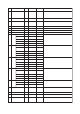
22 MODE_BLK
(DS-37)
– 0x08: Auto The mode parameter is a structured parameter composed of the
actual mode, the normal mode and the permitted mode.
Actual: Indicates the current operating condition.
Permit: Indicates the operating condition that the block is
allowed to take.
Normal: Indicates the operating condition that the block will
usually take.
Actual
–O/S bit, Auto bit
The permitted bit is
only available.
0x80: O/S,
0x08: Auto
Permitted
–
0x08: Auto
Normal
23 ALARM_SUM
(DS-42)
–0
Bit7 is only available.
The current alert status, unacknowledged status, unreported status
and disabled status of the alarms associated with the function block.
Current
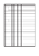
24 CALIBR_FACTOR O/S
O/S
1.00000.01 to 3.0000 Gain compensation value for the detector, so that flow indication is
accurate.
This parameter means the meter factor of low frequency side
(LOW_MF).
This parameter must not be downloaded by the operator.
25
26
LOW_FLOW_CUTOFF 0The value which
corresponds to 0 to
10% of PV_SPAN
is permitted.
Set the low cut range corresponding 0 to 10 % of the large absolute
value between PV_SCALE.Array1 and PV_SCALE.Array2.
This value must be set to the lower switching point because this
function has a hysterisis.
O/SMEASUREMENT_MODE
0: Unidirectional
0: Unidirectional
1: Bidirectional
Set the mode of the flow measurement,either unidirectional or
bidirectional.
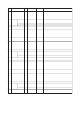
27 O/SFLOW_DIRECTION 0: Positive0: Positive
1: Negative
Assign an arbitrary positive or negative sign to the measured PV
value.
28 O/SZERO_POINT 0.000-999.9 to 999.9 This function shows the current zero point compensation value for
the sensor.
This parameter is used to display the results obtained from
ZERO_POINT_ADJUST . Specifically, the correction values
displayed, and it is also possible to directly enter correction values.
This parameter must not be downloaded by the operator.
29 AutoZERO_POINT_ADJUST 0: Cancel0: Cancel
1: Execute
This parameter executes the automatic zero adjustment function: If
“Execute” is selected, this function will be started.
“Now Auto Zero Executing...” is indicated while the Auto Zero
function is being carried out and After finishing the adjustment, this
parameter is set to “Cancel”. The result of the automatic zero
adjustment is confirmed using ZERO_POINT , and if the result
exceeds the rated value, the warning “82: Auto Zero Wng” will be
displayed.
30 O/SZERO_POINT_UNIT 1062: mm/s1062: mm/s This parameter is used in order to select the unit for zero point.
31 O/SNOMINAL_SIZE Specified at
the time of
order
0.99 to 3000.10 (mm)
0.01 to 120.10 (inch)
This parameter is used in order to set the size (diameter) of the
sensor (flow tube).
If the setting value exceeds the valid range, the warning “72:Size Set
Err” will be displayed.
–0for future use
Unacknow-
ledged
–0for future use
Unreported
–0for future use
Disabled