User’s Manual ADMAG AXF Series FOUNDATION Fieldbus Communication Type Magnetic Flowmeter IM01E20F02-01E IM01E20F02-01E Yokogawa Electric Corporation 3rd Edition
CONTENTS CONTENTS 1. INTRODUCTION ............................................................................................ 1-1 Regarding This Manual ................................................................................. 1-1 1.1 Safe Use of This Product .................................................................... 1-2 1.2 Warranty .............................................................................................. 1-3 1.3 Combination Remote Flowtubes ........................
CONTENTS 6. IN-PROCESS OPERATION .......................................................................... 6-1 6.1 6.2 Mode Transition .................................................................................. 6-1 Generation of Alarm ............................................................................ 6-1 6.2.1 Indication of Alarm ....................................................................... 6-1 6.2.2 Alarms and Events ...........................................................
CONTENTS APPENDIX 2. INTEGRATOR (IT) BLOCK ....................................................... A-6 A2.1 Schematic Diagram of Integrator Block .............................................. A-6 A2.2 Input Process Section ......................................................................... A-7 A2.2.1 Determining Input Value Statuses ............................................... A-7 A2.2.2 Converting the Rate ..................................................................... A-7 A2.2.
CONTENTS APPENDIX 5. PID BLOCK .............................................................................. A-32 A5.1 Function Diagram .............................................................................. A-32 A5.2 Functions of PID Block ..................................................................... A-32 A5.3 Parameters of PID Block .................................................................. A-33 A5.4 PID Computation Details .........................................................
1. INTRODUCTION 1. INTRODUCTION This manual is for the ADMAG AXF Series Magnetic Flowmeter Remote Converter FOUNDATION fieldbus Communication Type. The FOUNDATION fieldbus communication type is based on the same ADMAG AXF technology used in the BRAIN/HART communication type, and is similar to the communication types in terms of basic performance and operation. This manual describes only those topics that are required for operation of the FOUNDATION fieldbus communication type.
1. INTRODUCTION 1.1 • The protective grounding must be connected securely at the terminal with the mark to avoid danger to personnel. Safe Use of This Product For the safety of the operator and to protect the instrument and the system, please be sure to follow this manual’s safety instructions when handling this instrument. If these instructions are not heeded, the protection provided by this instrument may be impaired. In this case, Yokogawa cannot guarantee that the instrument can be safely operated.
1. INTRODUCTION 1.2 Warranty 1.3 • The warranty shall cover the period noted on the quotation presented to the purchaser at the time of purchase. Problems occurring during the warranty period shall basically be repaired free of charge. Combination Remote Flowtubes IMPORTANT • The AXFA14 Magnetic Flowmeter Converter should be used in combination with the following remote flowtubes: AXF002ⵧ-P to AXF400ⵧ-P Other flowtubes (size 500 to 2600 mm) cannot be combined with the AXFA14 converter.
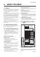
2. ABOUT FIELDBUS 2. ABOUT FIELDBUS 2.1 Outline Fieldbus is a widely used bi-directional digital communication protocol for field devices that enable the simultaneous output to many types of data to the process control system. The AXF Series Fieldbus communication type employs the specification standardized by The Fieldbus Foundation, and provides interoperability between Yokogawa devices and those produced by other manufacturers.
2. ABOUT FIELDBUS 2.4 Wiring System Configuration The number of devices that can be connected to a single bus and the cable length vary depending on system design. When constructing systems, both the basic and overall design must be carefully considered to achieve optimal performance.
3. GETTING STARTED 3. GETTING STARTED Fieldbus is fully dependent upon digital communication protocol and differs in operation from conventional 4 to 20 mA transmission and the BRAIN communication protocol. It is recommended that novice users use field devices in accordance with the procedures described in this section. The procedures assume that field devices will be set up on a bench or in an instrument shop. Refer to Yokogawa when making arrangements to purchase the recommended equipment.
3. GETTING STARTED 3.2 Host Setting 0x00 To activate Fieldbus, the following settings are required for the host. 0x0F 0x10 Not used 0x13 0x14 Bridge device LM device V(FUN) IMPORTANT Unused Do not turn off the power immediately after setting. When the parameters are saved to the EEPROM, the redundant processing is executed for an improvement of reliability.
3. GETTING STARTED 3.3 Bus Power ON 3.4 Integration of DD Turn on the power of the host and the bus and also the power for the AXF. Where the AXF is equipped with an LCD indicator, first all segments are lit, then the display begins to operate. If the host supports DD (Device Description), the DD of the AXF needs to be installed. Check if host has the following directory under its default DD directory. Using the host device display function, check that the AXF is in operation on the bus.
3. GETTING STARTED 3.6 Continuous Record of Values If the host has a function that continuously records the indications, use this function to list the indications (values). Depending on the host being used, it may be necessary to set the schedule of Publish (the function that transmits the indication on a periodic basis). 3.7 Generation of Alarm Generation of an alarm can be attempted from AXF. Block alarm, Output limit alarm, and Update alarm are informed to the host.
4. CONFIGURATION 4. CONFIGURATION This chapter describes how to adapt the function and performance of the AXF to suit specific applications. Because multiple devices are connected to Fieldbus, it is important to carefully consider the device requirements and settings when configuring the system. The following steps must be taken. (1)Network design Determines the devices to be connected to Fieldbus and checks the capacity of the power supply.
4. CONFIGURATION bus control function allocated from a larger address number (247) side respectively. Place the AXF in the range of the BASIC device. When the AXF is used as Link Master, place the AXF in the range of the LM device. Set the range of addresses to be used to the LM device. Set the following parameters. Table 4.2 Operation Parameter Values of the AXF to be Set to LM Devices Symbol V (ST) Parameters Slot-Time Table 4.
4. CONFIGURATION A maximum of 30 ms is taken for execution of AI block. For scheduling of communications for combination with the next function block, the execution is so arranged as to start after a lapse of longer than 30 ms. In no case should function blocks of the AXF be executed at the same time (execution time is overlapped). Figure 4.3 shows an example of schedule based on the loop shown in Figure 4.2. 4.
4. CONFIGURATION 4.5 Communication Setting Table 4.4 VCR Static Entry Subindex To set the communication function, it is necessary to change the database residing in SM-VFD. Parameter 1 FasArTypeAndRole Indicates the type and role of communication (VCR). The following 4 types are used for AXF. 0x32: Server (Responds to requests from host.) 0x44: Source (Transmits alarm or trend.) 0x66: Publisher (Sends AI block output to other blocks.) 0x76: Subscriber (Receives output of other blocks by PID block.
4. CONFIGURATION Subindex Parameter 4.6 Block Setting Description Set the parameter for function block VFD. 12 FasDllSubsriberTime WindowSize 13 FasDllSubscriber Not used for AXF. SynchronizationDlcep 14 FmsVfdId Sets VFD for AXF to be used. 0x1: System/network management VFD 0x1234: Function block VFD 15 FmsMaxOutstanding ServiceCalling Set 0 to Server. It is not used for other applications. 16 FmsMaxOutstanding ServiceCalled Set 1 to Server. It is not used for other applications.
4. CONFIGURATION 4.6.2 Trend Object SMIB (System Resource Transducer Management block block Information Base) It is possible to set the parameter so that the function block automatically transmits Trend. AXF has seven Trend objects, six of which are used for Trend in analog mode parameters and one is used for Trend in discrete mode parameter. A single Trend object specifies the trend of one parameter.
4. CONFIGURATION Table 4.
4. CONFIGURATION Table 4.
4. CONFIGURATION Table 4.14 View Object for DI (DI1, DI2) Function Block Table 4.
4. CONFIGURATION Table 4.16 View Object for AR Function Block Table 4.
4. CONFIGURATION Table 4.
5. EXPLANATION OF BASIC ITEMS 5. EXPLANATION OF BASIC ITEMS 5.1 Outline This chapter describes basic TR (Transducer block), AI, and DI function block parameter setting, displays of the integral indicator. Refer to Appendixes other function blocks and LM function. 5.2 Setting and Changing Parameters for the Whole Process IMPORTANT This chapter contains information on how to adapt the function and performance of the ADMAG AXF to suit specific applications.
5. EXPLANATION OF BASIC ITEMS 5.3 Transducer Block Parameters The transducer block sets functions specific to the flow rate measurement of the ADMAG AXF. Figure5.3.1 presents the diagram of the Transducer block. Flow rate operation Dual freq. operation Rate limit damping Lowcut Limit check SENSOR PRIMARY_VALUE (Channel1) LIMSW_1_VALUE_D (Channel2) LIMSW_2_VALUE_D (Channel3) Adhesion check Historical records Equipment information SWITCH_1_VALUE_D (Channel4) SWITCH_2_VALUE_D (Channel5) F0501.
5. EXPLANATION OF BASIC ITEMS DISPLAY_SELECT1, 2, 3: Table 5.3.1 DISPLAY SELECT DISPLAY_SELEC T 1 The display content for the display unit's first line. DISPL AY_SELE CT 2 DISPL AY_SELE CT 3 The display content for the display unit's second line. The display content for the display unit's third line.
5. EXPLANATION OF BASIC ITEMS 5.4 AI Function Block Parameters AI Function block parameters can be read or set from the host. Figure5.4.1 presents the diagram of AI Function block. Alarms HI,HI_HI LO,LO_LO IO_OPTS.Low cutoff SIMULATE.Enable LOW_CUT =1 (Enable) FIELD_VAL.Value Simulate SIMULATE.Transducer Value L_TYPE PV.Value Disable Enable Ind.Sqr Root Scaling XD_SCALE ✓/100 /100 AUTO Scaling OUT_SCALE Filter PV_FTIME OUT Indirect Simulate SIMULATE.Simulate Value Direct MODE_BLK.
5. EXPLANATION OF BASIC ITEMS OUT: This parameter contains the current measurement value from Transducer Block or configuration adjusted engineering unit and the belonging state in AUTO MODE. OUT contains the value and status set by an operator in MAN MODE.
5. EXPLANATION OF BASIC ITEMS Table 5.4.
5. EXPLANATION OF BASIC ITEMS 5.5 DI Function Block Parameters DI Function block parameters can be read or set from the host. Figure5.5.1 presents the diagram of DI Function block. PV_D CHANNEL Simulate Optional Filter SIMULATE_D Invert PV_FTIME Output OUT_D FIELD_VAL_D Alarms DISC MODE F0503.eps Figure 5.5.1 Diagram of DI Function Block ADMAG AXF contains two DI function blocks, which individually transfer the "Flow switch" and "Adhesion Alarm/warning" generated by the transducer block.
5. EXPLANATION OF BASIC ITEMS 5.6 Integral LCD Indicator Flow Rate Flow rate is displayed together with the units set in XD_SCALE, the maximum number of figures is six. Employing 32*132 full dot matrix backlit LCD, various display can be obtained. FR 5.6.1 Flow Data Display By the transducer block parameters setting in DISPLAY_SELECT1, 2, 3 as described in 5.3, up to three lines display can be made among the following data.
5. EXPLANATION OF BASIC ITEMS Flow Rate Unit Display on LCD Flow Rate Unit Display is shown by the following table corresponding to the XD_SCALE Units Codes. Table 5.6.
5. EXPLANATION OF BASIC ITEMS Arithmetic Out The display is given in the same manner as Integrator Out, decimal point is set by "AR:OUT_RANGE.Decimal_Point". FR 123.456 l / h L e v e l : 2 A D H F0515.eps AR:OUT_RANGE.Decimal_Point 0 1 2 3 4 5 6 7 Other Desimal Point Location 0 1 2 3 4 5 6 7 0 Example 12345678 1234567.8 123456.78 12345.678 1234.5678 123.45678 12.345678 1.2345678 12345678 Level1 : Adhesion Level2 Adh Measure Value > Adhesion Level1 FR 123.456 l / h L e v e l : 1 T0513.
5. EXPLANATION OF BASIC ITEMS Alarm Display 100.123 1 2 3 4 5 6 F o u n d a t i o n FR l / h I T 2 M l F i e l d b u s C O M Alarm generated P r 3 F i f l o 1 l u c e s s A l a r m : E mp t y P i p e l f l o w t u b e i d 100.123 1 2 3 4 5 6 F o u n d a t i o n w i t h FR l / h I T 2 M l F i e l d b u s C O M Data is fixed at the value when alarm generated P r 3 F i f l o 1 l u c e s s A l a r m : E mp t y P i p e l f l o w t u b e i d 100.
5.
5. EXPLANATION OF BASIC ITEMS FR 999. 999 123456 M l 999. 999 l / h l / h I T 1 FR 1 2 3 5 5 6 M l 8 4 : D i s p O v e r Wn g I T 1 999. 999 123656 FR l / h I T 1 M l F0520.eps Warning Message On the Integral LCD indicator following messages are displayed when warning is generated. Table 5.6.
6. IN-PROCESS OPERATION IN-PROCESS OPERATION This chapter describes the procedure performed when changing the operation of the function block of the AXF in process. 6.1 Mode Transition When the function block mode is changed to Out_Of_Service, the function block pauses and a block alarm is issued. When the function block mode is changed to Manual, the function block suspends updating of output values. In this case alone, it is possible to write a value to the OUT parameter of the block for output.
6. IN-PROCESS OPERATION 6.3 Simulation Function The simulation function simulates the input of a function block and lets it operate as if the data was received from the transducer block. It is possible to conduct testing for the downstream function blocks or alarm processes. A SIMULATE_ENABLE switch is mounted in the AXF amplifier. This is to prevent the accidental operation of this function. When this is switched on, simulation is enabled. (See Figure 6.2.
7. DEVICE INFORMATION 7. DEVICE INFORMATION 7.1 DEVICE STATUS Device status for the AXF are indicated by using parameter DEVICE_STATUS_1 to DEVICE_STATUS_7 (index 1045 to 1052) in Resource Block. Table 7.1 Contents of DEVICE_STATUS_1 (Index 1045) Indicator Table 7.2 Contents of DEVICE_STATUS_2 (Index 1046) bit Hex description bit Hex 0 0x00000001 Link Obj.16/32 not open 0 0x00000001 10:uP Fault Indicator Microprocessor (CPU) failure description 1 0x00000002 Link Obj.
7. DEVICE INFORMATION Table 7.3 Contents of DEVICE_STATUS_3 (Index 1047) Table 7.5 Contents of DEVICE_STATUS_5 (Index 1049) bit Hex bit Hex 0 0x00000001 30:Sig Overflow Input signal error 0 0x00000001 50:Span > 10m/s Span flow velocity setting is 11 m/s or more 1 0x00000002 31:Empty Pipe Flowtube is not filled with fluid 1 0x00000002 51:Span < 0.1m/s Span flow velocity setting is 0.
7. DEVICE INFORMATION Table 7.
7. DEVICE INFORMATION 7.2 Status of each parameter in failure mode Following tables summarize the value of AXF parameters and LCD display indicates an Alarm. Table 7.
8. PARAMETER LISTS 8. PARAMETER LISTS Note: The Write Mode column contains the modes in which each parameter is write enabled. O/S: Write enabled in O/S mode. MAN: Write enabled in Man mode and O/S mode. AUTO: Write enabled in Auto mode, Man mode, and O/S mode. 8.
8. PARAMETER LISTS Relative Index Index Parameter Name Factory Default Write Mode Explanation Used to select resource block options defined in FEATURES. 18 1018 FEATURE_SEL 0x000a Auto 19 1019 CYCLE_TYPE 0x0001 - 20 1020 CYCLE_SEL 0x0001 Auto 21 1021 MIN_CYCLE_T 3200 - Time duration of the shortest cycle interval of which the resource is capable. 22 1022 MEMORY_SIZE 0 - Available configuration memory in the empty resource. To be checked before attempting a download.
8. PARAMETER LISTS Relative Index Index Parameter Name Factory Default Write Mode Explanation 45 1045 DEVICE_STATUS_1 0 - Device status for details, refer to Table 7.1. 46 1046 DEVICE_STATUS_2 0 - Device status for details, refer to Table 7.2. 47 1047 DEVICE_STATUS_3 0 - Device status for details, refer to Table 7.3. 48 1048 DEVICE_STATUS_4 0 - Device status for details, refer to Table 7.4. 49 1049 DEVICE_STATUS_5 0 - Device status for details, refer to Table 7.5.
8. PARAMETER LISTS 8.2 Transducer Block Relative Index Index Parameter Name Factory Default 0 2000 BLOCK_HEADER 1 2001 ST_REV 2 2002 TAG_DESC 32 space characters 3 2003 STRATEGY 1 4 2004 ALERT_KEY 1 5 2005 MODE_BLK 6 2006 BLOCK_ERR Write Mode Explanation Information on this block such as Block Tag, DD Revision, Execution Time etc. 0 The revision level of the static data associated with the function block.
8. PARAMETER LISTS Relative Index Index Parameter Name Write Mode Explanation 1: linear with input O/S The linearization type of sensor output. AXF is "linear with input" 27 2027 28 2028 SECONDARY_ VALUE 29 2029 SECONDARY_ VALUE_UNIT 1061: m/s O/S N/A. For the future use. 30 2030 LANGUAGE 1: English Auto This parameter is used to select the language for use on the display. Now only 1: English is available.
8.
8. PARAMETER LISTS Relative Index Index Parameter Name 64 2064 65 2065 SWITCH_2_ VALUE_D 66 2066 SWITCH_2_TARGET 67 2067 68 2068 Factory Default SWITCH_1_TARGET 1: Adhesion Alarm Write Mode Explanation O/S This parameter selects the input channel used to LIMSW_1_VALUE_D. 1: Adhesion Alarm 2: Adhesion Warning Indicate the value of switch 2, which switches ON and OFF depending on the digital value of the target input parameter selected in SWITCH_2_TARGET.
8. PARAMETER LISTS Relative Index Index Parameter Name Factory Default Write Mode Explanation 85 2085 ALARM_SUM 86 2086 ADHESION_CHECK 1:No O/S Selects whether or not the adhesion diagnostic function will be carried out. (If the judgment value for Level 3 exceeds, a warning is displayed; and if the value for level 4 exceeds, an alarm is displayed. Valid range is 1: No, 2: Yes 87 2087 ADHESION_LEVEL1 0.
8. PARAMETER LISTS 8.3 AI Function Block Relative Index Index Parameter Name Factory Default Write Mode TAG="AI" O/S 0 - Explanation 0 4000 Block Hedder 1 4001 ST_REV 2 4002 TAG_DESC spaces Auto The user description of the intended application of the block 3 4003 STRATEGY 1 Auto The strategy field can be used to identify grouping of blocks. This data is not checked or processed by the block. Valid range is 0 to 65535.
8. PARAMETER LISTS Relative Index Index 19 4019 Parameter Name FIELD_VAL Factory Default Write Mode Bad - O/S - Raw value of the field device in percent of the PV range, with a status reflecting the Transducer condition, before signal characterization (L_TYPE), filtering (PV_FTIME), or low cut (LOW_CUT). Explanation 20 4020 UPDATE_EVT 1 (Acknowledged) - This alert is generated by any change to the static data.
8. PARAMETER LISTS 8.4 Dl Function Block Relative Index Index DI1 Index DI2 Parameter Name Factory Default Write Mode 0 6000 6100 Block Header 1 6001 6101 ST_REV 2 6002 6102 TAG_DESC spaces Auto The user description of the intended application of the block 3 6003 6103 STRATEGY 1 Auto Used by an upper-level system to identify grouping of the block. Not checked or processed by the block. Valid range is 0 to 65535.
9. GENERAL SPECIFICATIONS 9. 9.1 GENERAL SPECIFICATIONS STANDARD SPECIFICATIONS For items other than those described below, refer to IM 01E20D01-01E, IM 01E20C02-01E. Applicable Models: Integral Flowmeter AXF Remote Converter AXFA14 Output: Digital communication signal based on FOUNDATION fieldbus protocol.
9. GENERAL SPECIFICATIONS MODEL AND SUFFIX CODE Integral Flowmeter AXF: AXFⵧⵧⵧⵧ-Fⵧⵧⵧⵧⵧ-ⵧⵧⵧⵧ-ⵧⵧⵧ/ⵧ Remote Converter AXFA14: AXFA14ⵧ-Fⵧ-ⵧⵧ/ⵧ (Note1) “F” following the first dash indicates that the output is digital communication compliant with the FOUNDATION fieldbus protocol. 9.2 OPTIONAL SPECIFICATIONS For options other than below, refer to IM 01E20D01-01E and IM 01E20C02-01E (Optional codes C1, C2, C3, EM, G11 and G13 are unable to select).
9. GENERAL SPECIFICATIONS 9.3 TERMINAL CONNECTION CAUTION Integral Flowmeter AXF Do not connect to these terminals which are marked “CAUTION Don’t connect”. POWER SUPPLY - PB + L/+ N/- Terminal configuration F01.EPS Terminal wiring Terminal Symbols Description Functional grounding N/– L/+ FB+ FB– Power supply Fieldbus communication signal Protective grounding (Outside of the terminal) T06.EPS Remote Type Converter AXFA14 Terminal configuration N/L/+ EX1 EX2 C SA A B SB FB+ FBF02.
10. MAINTENANCE 10. MAINTENANCE For maintenance items, please refer to user’s manual IM 01E20D01-01E or IM 01E20C02-01E.
APPENDIX 1. APPLICATION, SETTING AND CHANGE OF BASIC PARAMETERS APPENDIX 1. APPLICATION, SETTING AND CHANGE OF BASIC PARAMETERS A1.1 Applications and Selection of Basic Parameters Setting Item (applicable parameters) Tag No.(PD_TAG) Calibration range setup (XD_SCALE of AI block) Output scale setup (OUT_SCALE of AI block) Summary Sets PD_Tag. Up to 32 alphanumeric characters can be set.
APPENDIX 1. APPLICATION, SETTING AND CHANGE OF BASIC PARAMETERS A1.2 Setting and Change of Basic Parameters IMPORTANT Do not turn the power OFF immediately after parameter setting. When the parameters are saved to the EEPROM, the redundant processing is executed for the improvement of reliability. If the power is turned OFF within 60 seconds after setting of parameters, changed parameters are not saved and may return to their original values.
APPENDIX 1. APPLICATION, SETTING AND CHANGE OF BASIC PARAMETERS A1.3 Setting the AI Function Block (4)Simulation Perform simulation of the AI function block by setting the desired value and status of the input to the block. The AI function block outputs the flow rate signals. REMOTE LOOP TEST SWITCH is written to SIM_ENABLE_MSG(index 1044) parameter of the resource block. (1)Setting the flow range Access the XD_SCALE parameter. Set the required unit in Unit Index of XD_SCALE.
APPENDIX 1. APPLICATION, SETTING AND CHANGE OF BASIC PARAMETERS A1.4 Setting the Transducer Block (4)Setting the LCD display Select the data to be displayed on the LCD indicator and the display refresh cycle. To access the AXF-specific functions in the transducer block, the Device Description (DD) for AXF needs to have been installed in the configuration tool used. Access the DISPLAY_SELECT1-3 parameter and set the item of display. ex.
APPENDIX 1. APPLICATION, SETTING AND CHANGE OF BASIC PARAMETERS A1.5 Setting the Integrator (IT) Function Block A1.6 Setting the DI Function Block The Integrator function block output the flow totalization. DI function blocks output limit switch signals received from the transducer block. (1)Setting the unit of totalization Two DI blocks (DI1 and DI2) in each AXF have independent parameters. Set up the parameters of each DI block you use, individually as necessary.
APPENDIX 2. INTEGRATOR (IT) BLOCK APPENDIX 2. INTEGRATOR (IT) BLOCK The Integrator (IT) block adds two main inputs and integrates them for output. The block compares the integrated or accumulated value to TOTAL_SP and PRE_TRIP and generates discrete output signals OUT_TRIP or OUT_PTRIP when the limits are reached. OUT.
APPENDIX 2. INTEGRATOR (IT) BLOCK A2.2 Input Process Section When executed, the Integrator block first performs input processing in the order of: "Determining input status" → "Converting Rate or Accum" → "Determining the input flow direction" Switching between Convert Rate and Convert Accum is made using bit 0 (for IN_1) or bit 1 (for IN_2) of INTEG_OPTS. INTEG_OPTS is one of the system parameters and should be set by the user. The values of IN_1 and IN_2 are not retained if the power is turned OFF. A2.2.
APPENDIX 2. INTEGRATOR (IT) BLOCK A2.2.3 Converting Accumulation This following describes an example of accumulation conversion. In accumulation conversion, the difference between the value executed previously and the value executed this time is integrated or accumulated. This conversion applies when the output of a function block used as a counter is input to the input process of the Integrator block.
APPENDIX 2. INTEGRATOR (IT) BLOCK A2.3.2 Addition The following three options are available for addition: • TOTAL: Adds two argument values as is. • FORWARD: Adds two argument values, regarding a negative value as "0." • REVERSE: Adds two argument values, regarding a positive value as "0." You can choose these options using bit 2 and bit 3 of INTEG_OPTS as follows: Bit 2 of INTEG_OPTS (Flow Forward) Bit 3 of INTEG_OPTS (Flow Reverse) Adder Options H H TOTAL L H L L L H TOTAL FORWARD REVERSE TA0202.
APPENDIX 2. INTEGRATOR (IT) BLOCK Table A2.
APPENDIX 2. INTEGRATOR (IT) BLOCK A2.5 Output Process A2.5.1 Status Determination There are the following three output parameters: The same criteria for determining the status of the output of the Integrator block are used in common for the above three parameters. 1. OUT 2. OUT_TRIP 3. OUT_PTRIP Parameters OUT_TRIP and OUT_PTRIP are used only when INTEG_TYPE is a value from 1 to 4. In case of Integrator block related memory failed, the status of OUT, OUT_TRIP, OUT_PTRIP becomes “Bad-Device Failure”.
APPENDIX 2. INTEGRATOR (IT) BLOCK A2.5.2 Determining the Output Value Total: Total of integrated values. This value is retained even if INTEG_TYPE is changed during integration (in AUTO). The value of OUT.Value is determined as follows: 䊉 For counting up OUT = integration start value (0) + Total 䊉 For counting down OUT = integration start value (TOTAL_SP) Total If OUT is rewritten in the MAN mode, integration starts with the value rewritten in MAN mode after the mode was returned to AUTO.
APPENDIX 2. INTEGRATOR (IT) BLOCK A2.5.3 Mode Handling Mode Action Automatic (AUTO) Output Normal action Normal output Integration calculation is stopped. Manual (MAN) OUT will not be updated unless you Out of Service (O/S) set a value to it. No reset is accepted. You may rewrite a value in OUT. If no value is rewritten, the value just before running in AUTO is held. When the mode returns to AUTO, integration starts with the written value or the value just before running in AUTO. TA0204.
APPENDIX 2. INTEGRATOR (IT) BLOCK A2.6.3 Reset Process ii Carry (bit 6 of INTEG_OPTS) The basic reset process sequence is as follows: If this option is enabled while INTEG_TYPE is UP_AUTO or DN_AUTO, the value exceeding the threshold at a reset will be carried into the next integration. 1.) Snapshot 2.) Clearing the integrated values 3.) Reset count increment 4.) Judging OUT_TRIP and OUT_PTRIP (see A2.5) If INTEG_TYPE is any setting other than UP_AUTO or DN_AUTO, this option is irrelevant.
APPENDIX 2. INTEGRATOR (IT) BLOCK A2.
APPENDIX 2. INTEGRATOR (IT) BLOCK Index Parameter Name Initial Value View Write Mode 1 2 3 4 Definition 4 Specify the period at which a periodic reset is made. 30 CLOCK_PER 31 PRE_TRIP 32 N_RESET 0.0 4 4 Indicates the number of resets in the range of 0 to 999999. 33 PCT_INCL 0.
APPENDIX 3. ARITHMETIC (AR) BLOCK APPENDIX 3. ARITHMETIC (AR) BLOCK The Arithmetic (AR) block switches two main inputs of different measurement ranges seamlessly and combines the result with three auxiliary inputs through the selected compensation function (10 types) to calculate the output. A3.1 Schematic Diagram of Arithmetic Block The diagram below shows the Arithmetic block schematic. FA0301.EPS Figure A3.
APPENDIX 3. ARITHMETIC (AR) BLOCK A3.2 Input Section PV is a parameter with status information, and PV status is determined by the value of “g.” There are five inputs: IN and IN_LO main inputs and IN_1, IN_2, and IN_3 auxiliary inputs. If “g” < 0.5 → The status of IN_LO is used. If “g” 0.5 → The status of IN is used. IN and IN_LO are intended to connect devices with different measurement ranges and allow the use of switching a measurement range by selecting the measuring device.
APPENDIX 3. ARITHMETIC (AR) BLOCK A3.2.3 INPUT_OPTS · If the status of IN is anything other than “good” and that of “IN_LO” is “good” INPUT_OPTS has an option that handles an input with “uncertain” or “bad” status as a “good” status input. Function Bit 0 Handles IN as a “good” status input if its status is “uncertain.” 1 Handles IN_LO as a “good” status input if its status is “uncertain.” 2 Handles IN_1 as a “good” status input if its status is “uncertain.
APPENDIX 3. ARITHMETIC (AR) BLOCK A3.3 Computation Section A3.3.1 Computing Equations This subsection shows computing equations used in the computation section: A3.3.2 Compensated Values In computing equations 1) to 5) in A3.3.1, the value “f” is restricted by the COMP_HI_LIM or COMP_LO_LIM parameter.
APPENDIX 3. ARITHMETIC (AR) BLOCK A3.4.1 Mode Handling Mode A3.4.2 Status Handling Output Auto OUT = PRE_OUT MAN For OUT, the OUT value in the Auto mode just before change to MAN or O/S is retained. O/S TA0303.EPS The setting of INPUT_OPTS is applied to the input status. When INPUT_OPTS is applied, there are cases where the PV status becomes “good” even if the status of main inputs is “uncertain” or the status of auxiliary inputs is “uncertain” or “bad.
APPENDIX 3. ARITHMETIC (AR) BLOCK A3.5 List of the Arithmetic Block Parameters View 1 2 3 4 Relative Index Parameter 0 BLOCK_HEADER 1 ST_REV 2 TAG_DESC Null 3 STRATEGY 1 4 ALERT_KEY 5 MODE_BLK AUTO 4 4 A universal parameter representing the operation status of the Arithmetic block. It consists of the Actual, Target, Permit, and Normal modes. 6 BLOCK_ERR 0 2 2 Indicates the error status relating to the Arithmetic block.
APPENDIX 3. ARITHMETIC (AR) BLOCK Relative Index Parameter Write Mode Valid Range Initial Value View 1 2 3 4 Description / Remarks Computation algorithm identification no.
APPENDIX 4. LINK MASTER FUNCTIONS APPENDIX 4. LINK MASTER FUNCTIONS A4.1 Link Active Scheduler A link active scheduler (LAS) is a deterministic, centralized bus scheduler that can control communications on an H1 fieldbus segment. There is only one LAS on an H1 fieldbus segment. An AXF supports the following LAS functions. • PN transmission: Identifies a fieldbus device newly connected to the same fieldbus segment. PN is short for Probe Node.
APPENDIX 4. LINK MASTER FUNCTIONS A4.3 Transfer of LAS There are two procedures for an LM to become the LAS: • If the LM whose value of [V(ST)⫻V(TN)] is the smallest on a segment, with the exception of the current LAS, judges that there is no LAS on the segment, in such a case as when the segment has started up or when the current LAS has failed, the LM In the event that the current LAS in this segment (node address 0x14) fails, the LM with the address of 0x15 takes its place to become the LAS.
APPENDIX 4. LINK MASTER FUNCTIONS A4.4 LM Functions No. Function Description 1 LM initialization When a fieldbus segment starts, the LM with the smallest [V(ST) × V(TN)] value within the segment becomes the LAS. At all times, each LM is checking whether or not a carrier is on the segment. 2 Startup of other nodes (PN and Node Activation SPDU transmissions) Transmits a PN (Probe Node) message, and Node Activation SPDU message to devices which return a new PR (Probe Response) message.
APPENDIX 4. LINK MASTER FUNCTIONS A4.5 LM Parameters A4.5.1 LM Parameter List The tables below show LM parameters.
APPENDIX 4.
APPENDIX 4. LINK MASTER FUNCTIONS A4.5.2 Descriptions for LM Parameters The following describes LM parameters of an AXF transmitter. NOTE: Do not turn off the power to the AXF for 60 seconds after making a change to its parameter settings.
APPENDIX 4. LINK MASTER FUNCTIONS (8)DlmeBasicInfo Subindex (11)PlmeBasicInfo Size [bytes] Element 1 SlotTime 2 Indicates the capability value for V(ST) of the device. 2 PerDlpduPhlOverhead 1 V(PhLO) 3 MaxResponseDelay 1 Indicates the capability value for V(MRD) of the device. 4 ThisNode 1 V(TN), node address 5 ThisLink 2 V(TL), link-id 6 MinInterPduDelay 1 Indicates the capability value for V(MID) of the device.
APPENDIX 4. LINK MASTER FUNCTIONS Subindex Element Size [bytes] • 0xFF (true) to PrimaryLinkMasterFlagVariable (index 364) in the AXF. Description 1 Version 2 Indicates the version number of the LAS schedule downloaded to the corresponding domain. 2 Macrocycle Duration 4 Indicates the macro cycle of the LAS schedule downloaded to the corresponding domain. 3 TimeResolution 2 Indicates the time resolution that is required to execute the LAS schedule downloaded to the corresponding domain.
APPENDIX 5. PID Block APPENDIX 5. PID BLOCK A PID block performs the PID control computation based on the deviation of the measured value (PV) from the setpoint (SV), and is generally used for constant-setpoint and cascaded-setpoint control. A5.1 Function Diagram The figure below depicts the function diagram of a PID block.
APPENDIX 5. PID Block A5.3 Parameters of PID Block NOTE: In the table below, the Write column shows the modes in which the respective parameters can be written. A blank in the Write column indicates that the corresponding parameter can be written in all modes of the PID block. A dash (-) indicates that the corresponding parameter cannot be written in any mode.
APPENDIX 5. PID Block Index Parameter Name Default Write (factory setting) Valid Range Description Action to be performed in the event of mode shedding. SHED_OPT defines the changes to be made to MODE.BLK.target and MODE.BLK.actual when the value of RCAS_IN.status or ROUT_IN.status becomes Bad if .MODE_BLK.actual = RCas or ROut. See Section A5.17.1 for details. 34 SHED_OPT 0 35 RCAS_OUT 0 --- Remote setpoint sent to a computer, etc.
APPENDIX 5. PID Block A5.4 PID Computation Details A5.5 Control Output The final control output value, OUT, is computed based on the change in control output ∆MVn, which is calculated at each control period in accordance with the aforementioned algorithm. The PID block in an EJX performs the velocity type output action for the control output. A5.4.
APPENDIX 5. PID Block A5.8 Feed-forward Block Mode Feed-forward is an action to add a compensation output signal FF_VAL to the output of the PID control computation, and is typically used for feed-forward control. The figure below illustrates the action. IMan Initialization and manual mode, in which the control action is suspended. The PID block enters this mode when the specified condition is met (see Section A5.14).
APPENDIX 5. PID Block A5.10 Bumpless Transfer A5.12 External-output Tracking Prevents a sudden change in the control output OUT at changes in block mode (MODE_BLK) and at switching of the connection from the control output OUT to the cascaded secondary function block. The action to perform a bumpless transfer differs depending on the MODE_BLK values. External tracking is an action of outputting the value of the remote output TRK_VAL set from outside the PID block, as illustrated in the figure below.
APPENDIX 5. PID Block Options in CONTROL_OPTS A5.15 Manual Fallback Description Bypass Enable This parameter allows BYPASS to be set. SP-PV Track in Man Equalizes SP to PV when MODE_BLK.target is set to Man. SP-PV Track in ROut Equalizes SP to PV when MODE_BLK.target is set to ROut. SP-PV Track in LO or IMan Equalizes SP to PV when actual is set to LO or IMAN. SP-PV Track retained Target Equalizes SP to RCAS_IN when MODE_ BLK.target is set to RCas, and to CAS_IN when MODE_BLK.
APPENDIX 5. PID Block A5.17 Mode Shedding upon Computer Failure When the data status of RCAS_IN or ROUT_IN, which is the setting received from a computer as the setpoint SP, falls to Bad while the PID block is running in the RCas or ROut mode, the mode shedding occurs in accordance with the settings in SHED_OPT. If the RCAS_IN data is not renewed within the time specified by SHED_RCAS in resource block, the data status of RCAS_IN falls to Bad. A5.17.
APPENDIX 5. PID Block A5.19 Example of Block Connections A5.
APPENDIX 5.
APPENDIX 6. SOFTWARE DOWNLOAD APPENDIX 6. SOFTWARE DOWNLOAD A6.1 Benefits of Software Download This function enables you to download software to field devices via a FOUNDATION Fieldbus to update their software. Typical uses are to add new features such as function blocks and diagnostics to existing devices, and to optimize existing field devices for your plant. Update Program New Diagnostics I/O PID AI AI Figure A6.1 Concept of Software Downloading A6.2 Specifications Steady-state current: Max.
APPENDIX 6. SOFTWARE DOWNLOAD CAUTION NOTE The current dissipation of the target field device increases transitorily immediately after a download due to erasing of the FlashROM’s contents. Use a fieldbus power supply which has sufficient capacity to cover such increases in feed current. The download tool can not execute downloading during other system connects to the system/ network management VFD of the device. A6.
APPENDIX 6. SOFTWARE DOWNLOAD The device type is “000B” for the AXF . The software name is “ORIGINAL” or “UPDATE.” The former indicates an original file and the latter an update file. Whenever performing a download to update the device revision, obtain the original file. In general, an addition to the parameters or blocks requires a device revision update. A6.
APPENDIX 6. SOFTWARE DOWNLOAD A6.7 Troubleshooting For information on the download tool’s error messages, see also the software’s User’s Manual. Table A6.2 Problems after Software Update Symptom Cause Remedy An error occurs before starting a download, disabling the download. The selected download file is not for the selected field device. Check SOFTDWN_ERROR in the resource block and obtain the correct file. An error occurs after starting a download, disabling the download.
APPENDIX 6. SOFTWARE DOWNLOAD Table A6.
APPENDIX 6. SOFTWARE DOWNLOAD A6.9 System/Network Management VFD Parameters Relating to Software Download Table A6.5 System/Network Management VFD Parameters Write Mode: R/W = read/write; R = read only Index (SM) 400 410 420 430 440 Parameter Name DWNLD_PROPERTY DOMAIN_DESCRIPTOR DOMAIN_HEADER.1 DOMAIN_HEADER.
APPENDIX 6. SOFTWARE DOWNLOAD A6.10 Comments on System/Network Management VFD Parameters Relating to Software Download IMPORTANT Do not turn off the power to a field device immediately after changing parameter settings. Data writing actions to the EEPROM are dual redandant to ensure reliability. If the power is turned off within 60 seconds after setup, the parameters may revert to the previous settings.
APPENDIX 6. SOFTWARE DOWNLOAD (2) DOMAIN_DESCRIPTOR Sub Element Index 1 Size 1 Command Description (Bytes) Reads/writes software download commands. 1: PREPARE_FOR_DWNLD (instruction of download preparation) 2: ACTIVATE (activation instruction) 3: CANCEL_DWNLD (instruction of download cancellation) 2 State 1 Indicates the current download status.
REVISION RECORD Title: ADMAG AXF Series FOUNDATION Fieldbus Communication Type Magnetic Flowmeter Manual No.: IM 01E20F02-01E Edition Date 1st June 2006 2nd May 2007 Page – 1-2 Revised Item New publication (d) (1-4) Added the warning note of "Maintenance". Deleted the ATEX documentation. (2-1 to 2-9) Deleted the chapter of "2.HANDLING CAUTIONS". Changed the chapter number of other chapter. 6-2 6.3 Changed the Figure 6.2. Added the important note for SIMULATE_ENABLE Switch setting.