
Manual


Table Of Contents
- Contents
- 1. INTRODUCTION
- 2. HANDLING PRECAUTIONS
- 3. INSTALLATION
- 4. WIRING
- 5. BASIC OPERATING PROCEDURES (USING THE DISPLAY UNIT)
- 6. PARAMETER DESCRIPTION
- 6.1 Parameters
- 6.2 Parameter Lists
- 6.3 Parameter List Overview
- 6.4 Parameter Description
- (1) Menu B: Easy Setup items
- (2) Menu C: Basic Setting items
- (3) Menu D: Total Setting items
- (4) Menu E: Pulse Setting items
- (5) Menu F: Status Functions Setting items
- (6) Menu G: Alarm Setting items
- (7) Menu H: Display Setting items
- (8) Menu J: Auxiliary Function Setting items
- (9) Menu K: Diagnostic Function Setting items
- (10) Menu M: Automatic Zero AdjustmentFunction Setting items
- (11) Menu N: Loop Test Setting items
- (12) Menu P: Parameter Protection items
- 6.5 Alarm Functions
- 7. OPERATION VIA BRAIN TERMINAL (BT200)
- 8. OPERATION VIA HART COMMUNICATOR TOOL (HART 5)
- 9. ACTUAL OPERATION
- 10. MAINTENANCE
- 11. OUTLINE
- REVISION RECORD
IM 01E20C01-01E
9-3
9. ACTUAL OPERATION
When zero adjustment function has been completed,
the system automatically returns to the sub-item
selection screen (D).
NOTE
The results of M10: Auto Zero Exe can be
displayed using M11: Magflow Zero. Alterna-
tively, if the results of the automatic zero
adjustment exceed the rated value, the warn-
ing 82: Auto Zero Wng will be displayed.
9.1.2 Zero Adjustment via External Status Input
This section describes the procedure for zero adjustment via external status input. (For
more details regarding external status input, refer to Chapter 6: Parameter Description.)
CAUTION
In certain cases where the multiple range function is being used with other status
inputs, it may not be possible to perform settings for automatic zero adjustment.
For more details, refer to the description of multiple ranges from Chapter 6:
Parameter Description.
In order to carry out zero adjustment via external status input, it will be necessary to set
“Ext Auto Zero” using either F12: SI1 Function or F13: SI2 Function. The parameter
F12: SI1 Function will be used in the following description.
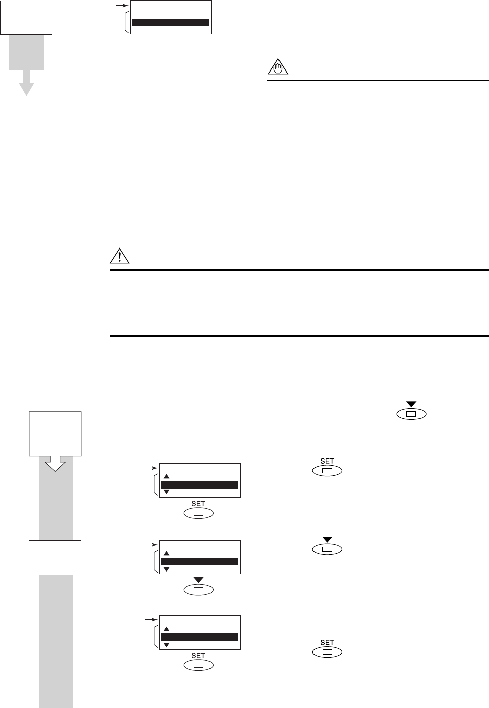
Once in Setting Mode, use the switch to
move the cursor to item F: Status Function.
Touch the switch to access Sub-item
Parameter Search Mode.
Touch the switch twice to move the cursor
to F12: SI1 Function.
The cursor has been moved to F12: SI1 Function
in this screen. (Sub-item selection screen (E))
Touch the switch to access Parameter
Replacement Mode.
F0902-1.EPS
Setting Mode
Major item
parameter
Setting Mode
E:Pulse Set
F:Status Function
G:Alarm
Major item
Sub-item
parameter
Major item
Sub-item
selection (E)
F:Status Function
41:Bi Direction Hys
10:SO1 Function
11:SO2 Function
F:Status Function
11:SO2 Function
12:SI1 Function
13:SI2 Function
X
2
Sub-item
Parameter
Search Mode
Start:
Major Item
Parameter
Search Mode
F0901-2.EPS
Major item
Sub-item
selection (D)
M:Adjustment
10:Auto Zero Exe
11:Magflow Zero
Sub-item
Parameter
Search Mode