
Manual


Table Of Contents
- Contents
- 1. INTRODUCTION
- 2. HANDLING PRECAUTIONS
- 3. INSTALLATION
- 4. WIRING
- 5. BASIC OPERATING PROCEDURES (USING THE DISPLAY UNIT)
- 6. PARAMETER DESCRIPTION
- 6.1 Parameters
- 6.2 Parameter Lists
- 6.3 Parameter List Overview
- 6.4 Parameter Description
- (1) Menu B: Easy Setup items
- (2) Menu C: Basic Setting items
- (3) Menu D: Total Setting items
- (4) Menu E: Pulse Setting items
- (5) Menu F: Status Functions Setting items
- (6) Menu G: Alarm Setting items
- (7) Menu H: Display Setting items
- (8) Menu J: Auxiliary Function Setting items
- (9) Menu K: Diagnostic Function Setting items
- (10) Menu M: Automatic Zero AdjustmentFunction Setting items
- (11) Menu N: Loop Test Setting items
- (12) Menu P: Parameter Protection items
- 6.5 Alarm Functions
- 7. OPERATION VIA BRAIN TERMINAL (BT200)
- 8. OPERATION VIA HART COMMUNICATOR TOOL (HART 5)
- 9. ACTUAL OPERATION
- 10. MAINTENANCE
- 11. OUTLINE
- REVISION RECORD
IM 01E20C01-01E
6-26
6. PARAMETER DESCRIPTION
[G13: High High Alarm] High-high alarm setting
This parameter sets the high-high limit (HH) alarm
value, and this is done using a % value of the maxi-
mum span.
A setting value of 110% indicates that the alarm is
disabled.
NOTE
Setting of -110% or 110% results in the corre-
sponding function being disabled; accordingly,
settings can be combined to implement only high
alarms or low alarms, etc.
Output Example 1
The high-high alarm (HH) is set to 90% or more of the
flow rate span; the low-low alarm (LL), to 20% or less;
the high alarm (H), to 80% or more; and the low alarm
(L), to 30% or less.
Settings are:
G10: Low Alarm = 30%
G11: High Alarm = 80%
G12: Low Low Alarm = 20%
G13: High High Alarm = 90%
0 Time (t)
HL
HH
SO1
SO2
LL
HH
AL
LL
High High Alarm
High Alarm
Instantaneous flow rate
Low Alarm
Low Low Alarm
20
30
50
80
90
100
[%]
Select “H/L Alarm” for F10: SO1 Function
Select “HH/LL Alarm” for F11: SO2 Function
Select “Closed (On) Act” for F14: SO1/2 Active Mode
Select “Open (Off) Act” for G20: Alm Out Act Mode
Select “Yes” for G33: Alm-HH/LL
F0610.EPS
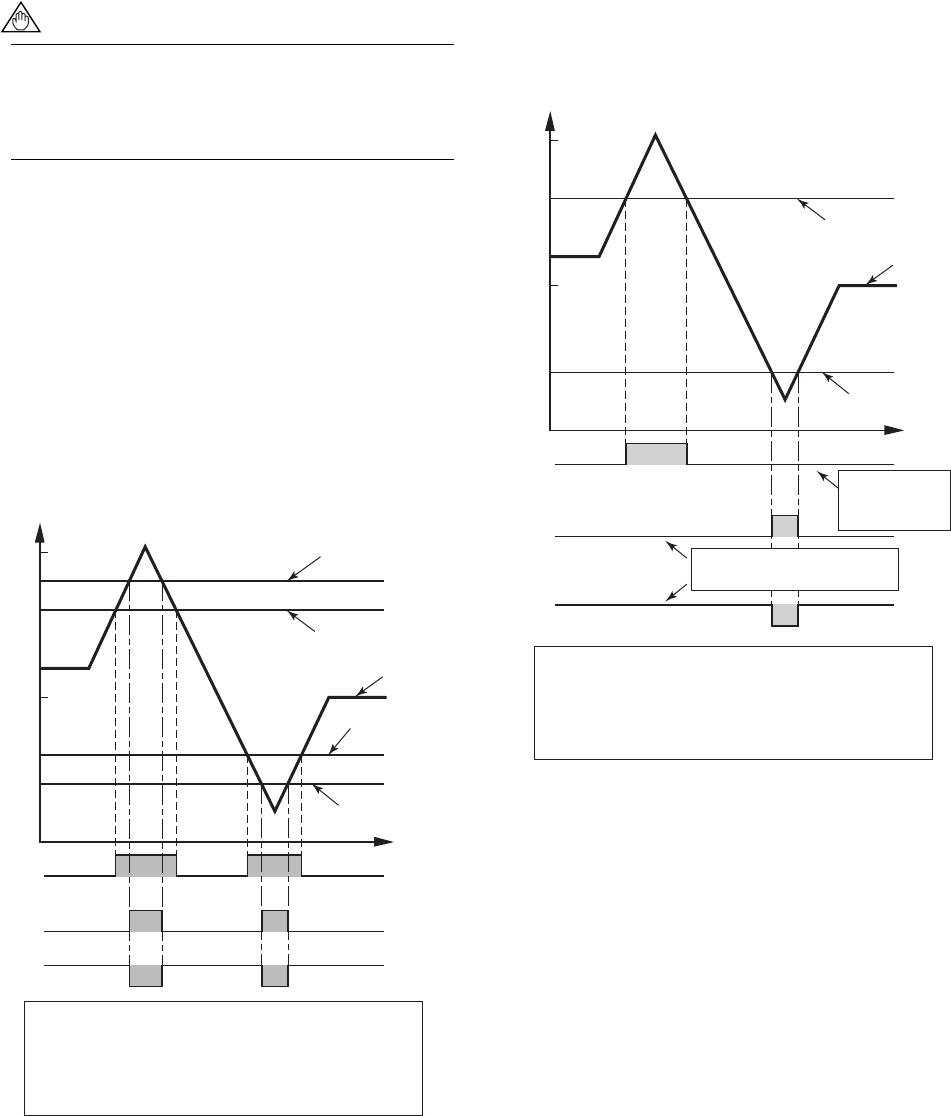
Output Example 2
The high alarm (H) is set to 80% or more of the flow
rate span; the low-low alarm (LL), to 20% or less.
Settings are:
G10: Low Alarm = -110%
G11: High Alarm = 80%
G12: Low Low Alarm = 20%
G13: High High Alarm = 110%
0 Time (t)
H
SO1
SO2
LL
AL
LL
Instantaneous flow rate
20
50
80
100
[%]
F0611.EPS
L Alarm set to
-110% indicates
that the alarm is
disabled.
High Alarm
Low Low Alarm
HH Alarm set to 110% indicates
that the alarm is disabled.
Select “H/L Alarm” for F10: SO1 Function
Select “HH/LL Alarm” for F11: SO2 Function
Select “Closed (On) Act” for F14: SO1/2 Active Mode
Select “Open (Off) Act” for G20: Alm Out Act Mode
Select “Yes” for G33: Alm-HH/LL