
Manual


Table Of Contents
- Contents
- 1. INTRODUCTION
- 2. HANDLING PRECAUTIONS
- 3. INSTALLATION
- 4. WIRING
- 5. BASIC OPERATING PROCEDURES (USING THE DISPLAY UNIT)
- 6. PARAMETER DESCRIPTION
- 6.1 Parameters
- 6.2 Parameter Lists
- 6.3 Parameter List Overview
- 6.4 Parameter Description
- (1) Menu B: Easy Setup items
- (2) Menu C: Basic Setting items
- (3) Menu D: Total Setting items
- (4) Menu E: Pulse Setting items
- (5) Menu F: Status Functions Setting items
- (6) Menu G: Alarm Setting items
- (7) Menu H: Display Setting items
- (8) Menu J: Auxiliary Function Setting items
- (9) Menu K: Diagnostic Function Setting items
- (10) Menu M: Automatic Zero AdjustmentFunction Setting items
- (11) Menu N: Loop Test Setting items
- (12) Menu P: Parameter Protection items
- 6.5 Alarm Functions
- 7. OPERATION VIA BRAIN TERMINAL (BT200)
- 8. OPERATION VIA HART COMMUNICATOR TOOL (HART 5)
- 9. ACTUAL OPERATION
- 10. MAINTENANCE
- 11. OUTLINE
- REVISION RECORD
IM 01E20C01-01E
4-9
4. WIRING
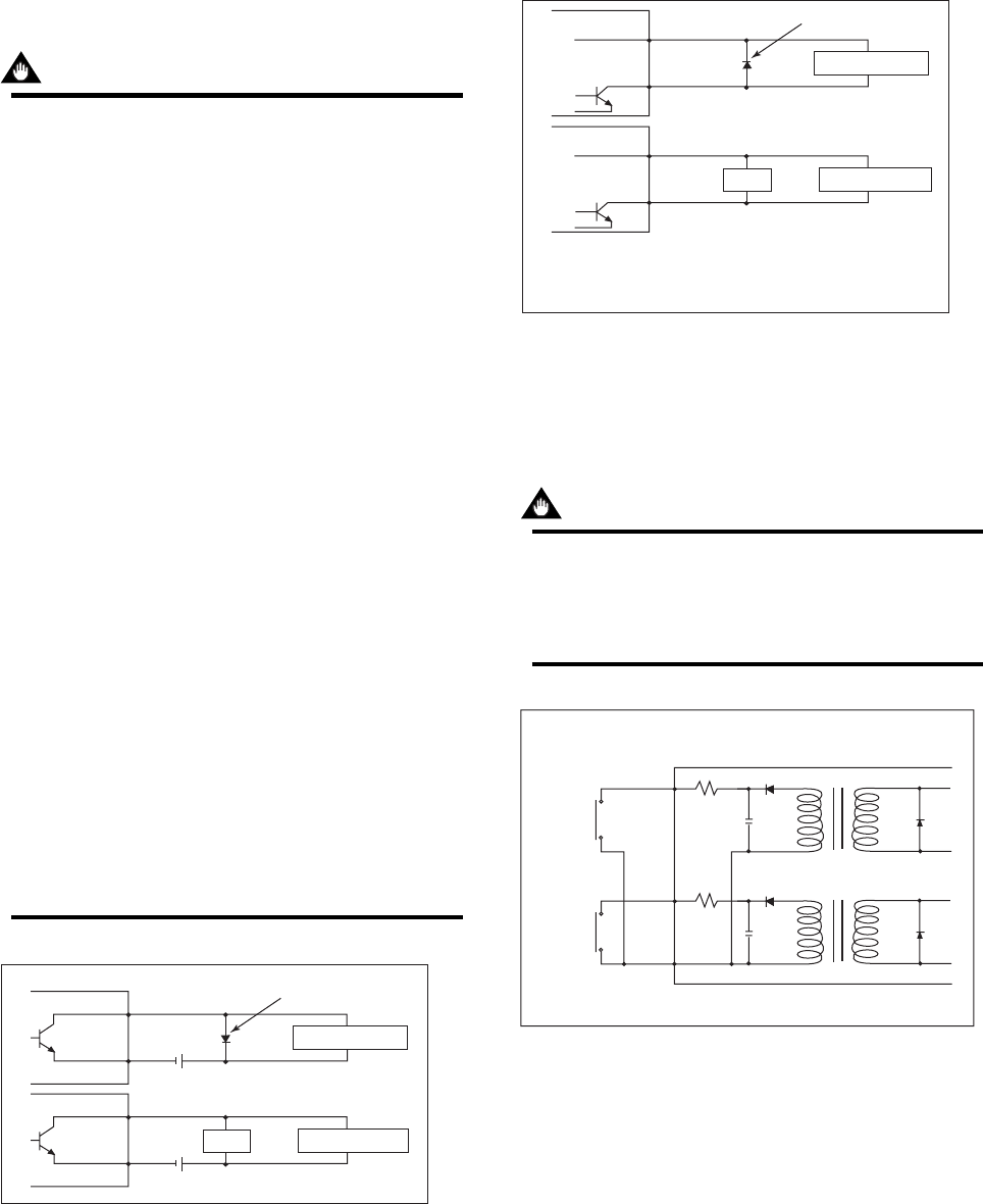
Pulse Output
IMPORTANT
• As this is a transistor contact (insulated type),
give attention to proper voltage and polarity
when wiring.
• Do not apply a voltage larger than 30V DC or a
current larger than 0.2A in order to prevent
damage to the instrument.
• When input filter constant of the electronic
counter is large in relation to the pulse width,
the signal will decrease and the count will not
be accurate.
• If the input impedance of the electronic counter
is large, an induction noise from the power
supply may result in inaccurate counts. Use a
shield cable or sufficiently reduce the input
impedance of the electronic counter within the
electromagnetic flowmeter pulse output specifi-
cation range.
• The active pulse output (Optional Code EM)
cannot be used in conjunction with the standard
pulse output.
• When the active pulse output (Optional Code
EM) is selected, do not be short-circuit between
the P+ and P– terminals to avoid damaging the
instrument.
• When the active pulse output (Optional code
EM) is selected, the range of pulse rate must
be set to 2 pps maximum.
• To avoid communication (BRAIN/ HART)
failure, it is recommended to use the shield
cable.
F0418.EPS
Mechanical Counter
Electronic Counter
Load
Protective diode
30V DC, 0.2A. max
PULSE OUT
PULSE OUT
AXFA11
AXFA11
P+
P-
P+
P-
Figure 4.4.10 Pulse Output Connection
F0419.EPS
Protective diode
PULSE OUT
PULSE OUT
AXFA11
AXFA11
P+
P-
P+
P-
Output voltage: 24 V DC 20%
• Current: 150 mA or less
Pulse rate: 0.0001 to 2 pps
Pulse width: 20, 33, 50, 100 ms
Mechanical Counter
Electronic Counter
Load
Figure 4.4.11 Active Pulse Output Connection
(Optional code EM)
Status Input
IMPORTANT
Status inputs are designed for use with no-
voltage (dry) contacts. Be careful not to connect
the status to any signal source carrying voltage.
Applying voltage may damage the input circuit.
AXFA11
SI1
+
SI2
+
COM
F0420.EPS
No-voltage status input
Closed: Less than 200 Ω
Open: More than 100 kΩ
Figure 4.4.12 Status Input Connection