
Manual
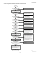


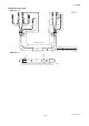
Table Of Contents
- Contents
- 1. INTRODUCTION
- 2. HANDLING PRECAUTIONS
- 3. INSTALLATION
- 4. WIRING
- 5. BASIC OPERATING PROCEDURES (USING THE DISPLAY UNIT)
- 6. PARAMETER DESCRIPTION
- 6.1 Parameters
- 6.2 Parameter Lists
- 6.3 Parameter List Overview
- 6.4 Parameter Description
- (1) Menu B: Easy Setup items
- (2) Menu C: Basic Setting items
- (3) Menu D: Total Setting items
- (4) Menu E: Pulse Setting items
- (5) Menu F: Status Functions Setting items
- (6) Menu G: Alarm Setting items
- (7) Menu H: Display Setting items
- (8) Menu J: Auxiliary Function Setting items
- (9) Menu K: Diagnostic Function Setting items
- (10) Menu M: Automatic Zero AdjustmentFunction Setting items
- (11) Menu N: Loop Test Setting items
- (12) Menu P: Parameter Protection items
- 6.5 Alarm Functions
- 7. OPERATION VIA BRAIN TERMINAL (BT200)
- 8. OPERATION VIA HART COMMUNICATOR TOOL (HART 5)
- 9. ACTUAL OPERATION
- 10. MAINTENANCE
- 11. OUTLINE
- REVISION RECORD
IM 01E20C01-01E
11-8
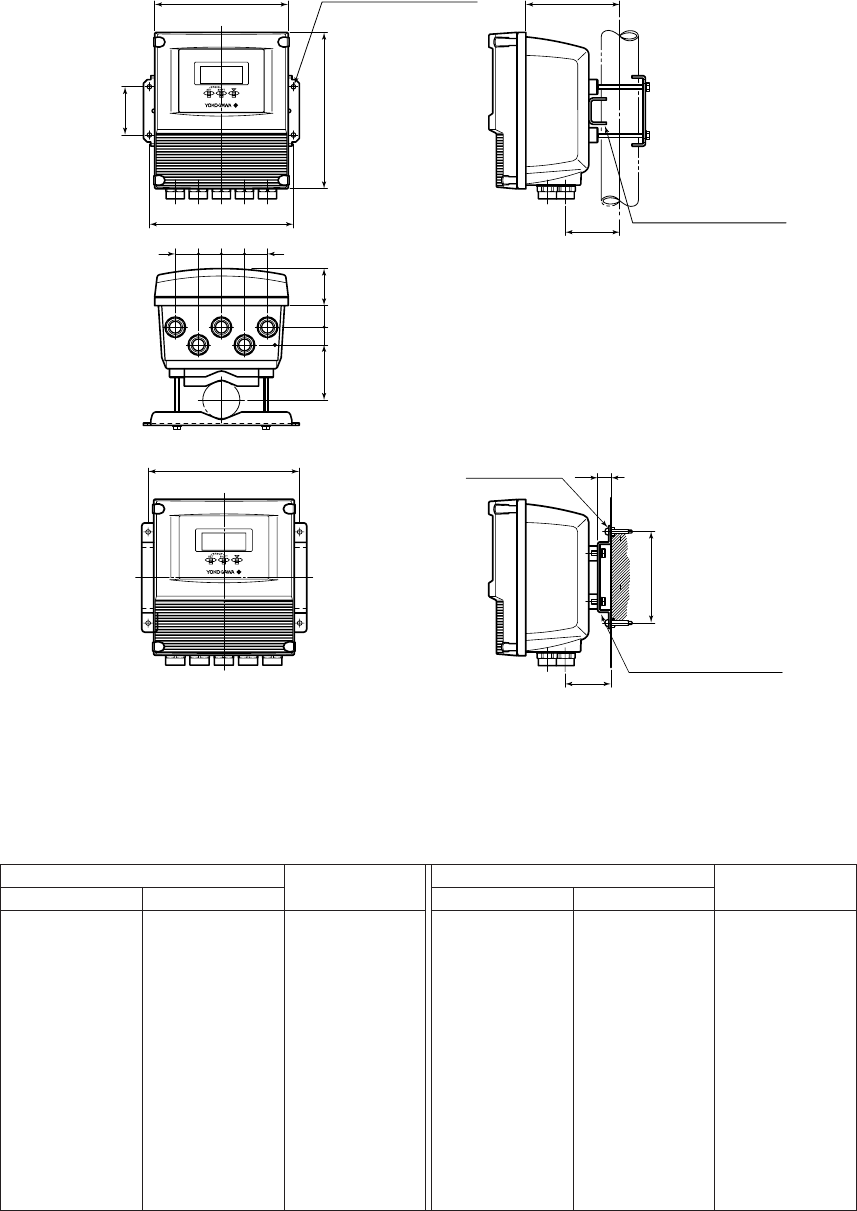
11. OUTLINE
● Remote Converter AXFA11G /RK (AM11 Replacement Bracket)
Pipe mounting
133.5(5.26)180(7.09)
194(7.64)
210(8.27)(80.5)
(3.17)
49
(1.93)
29
(1.14)
24
(0.94)
65(2.56)
(80.5)
(3.17)
31
(1.22)
31
(1.22)
31
(1.22)
31
(1.22)
FF0AXFA11E.EPS
Bracket for replacement
(For pipe mounting)
4-ø6(0.24)
(Surface mounting hole)
(190)
(7.48)
Bracket for replacement
(For surface mounting)
(62)
(2.44)
18(0.71)
Mouting Screw
*1
Surface mounting
(126.5)
(4.98)
*1: These screws must be
* provided by the user.
● Unless otherwise specified, difference in the dimensions are refer to the following table.
Above Equal or below Above Equal or below
Category of basic dimension
Category of basic dimension
Tolerance Tolerance
3 (0.12)
6 (0.24)
10 (0.39)
18 (0.71)
30 (1.18)
50 (1.97)
80 (3.15)
120 (4.72)
180 (7.09)
250 (9.84)
315 (12.40)
400 (15.75)
3 (0.12)
6 (0.24)
10 (0.39)
18 (0.71)
30 (1.18)
50 (1.97)
80 (3.15)
120 (4.72)
180 (7.09)
250 (9.84)
315 (12.40)
400 (15.75)
500 (19.69)
0.7 (0.03)
0.9 (0.04)
1.1 (0.04)
1.35 (0.05)
1.65 (0.06)
1.95 (0.08)
2.3 (0.09)
2.7 (0.11)
3.15 (0.12)
3.6 (0.14)
4.05 (0.16)
4.45 (0.18)
4.85 (0.19)
500 (19.69)
630 (24.80)
800 (31.50)
1000 (39.37)
1250 (49.21)
1600 (62.99)
2000 (78.74)
2500 (98.43)
630 (24.80)
800 (31.50)
1000 (39.37)
1250 (49.21)
1600 (62.99)
2000 (78.74)
2500 (98.43)
3150 (124.02)
5.5 (2.17)
6.25 (0.25)
7.0 (0.28)
8.25 (0.32)
9.75 (0.38)
11.5 (0.45)
14.0 (0.55)
16.5 (0.65)
Remarks: The numeric is based on criteria of tolerance class IT18 in JIS B 0401.
General tolerance in the dimensional outline drawing.
Unit : mm (approx.inch)