
Manual


Table Of Contents
- Contents
- 1. INTRODUCTION
- 2. HANDLING PRECAUTIONS
- 3. INSTALLATION
- 4. WIRING
- 5. BASIC OPERATING PROCEDURES (USING THE DISPLAY UNIT)
- 6. PARAMETER DESCRIPTION
- 6.1 Parameters
- 6.2 Parameter Lists
- 6.3 Parameter List Overview
- 6.4 Parameter Description
- (1) Menu B: Easy Setup items
- (2) Menu C: Basic Setting items
- (3) Menu D: Total Setting items
- (4) Menu E: Pulse Setting items
- (5) Menu F: Status Functions Setting items
- (6) Menu G: Alarm Setting items
- (7) Menu H: Display Setting items
- (8) Menu J: Auxiliary Function Setting items
- (9) Menu K: Diagnostic Function Setting items
- (10) Menu M: Automatic Zero AdjustmentFunction Setting items
- (11) Menu N: Loop Test Setting items
- (12) Menu P: Parameter Protection items
- 6.5 Alarm Functions
- 7. OPERATION VIA BRAIN TERMINAL (BT200)
- 8. OPERATION VIA HART COMMUNICATOR TOOL (HART 5)
- 9. ACTUAL OPERATION
- 10. MAINTENANCE
- 11. OUTLINE
- REVISION RECORD
IM 01E20C01-01E
11-7
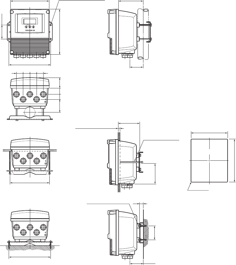
11. OUTLINE
■ EXTERNAL DIMENSIONS
● Remote Converter AXFA11G
Pipe mounting
120(4.72)180(7.09)
4-ø6 Hole
(Surface mounting hole)
194(7.64)
210(8.27)
65
(67)
(2.64)
194(7.64)
182(7.17)
Panel mounting
100(3.94)
1 to 10(0.04 to 0.39)
(Panel thickness)
Mounting Screw
(M6 100(3.94))
172(6.77)
R3 MAX
203(7.99)
Panel cutout
62
18(0.71)
Mounting Screw(M6)
Surface mounting
T08.EPS
(2.56)
(2.44)
105
(4.13)
65
(2.56)
(67)
(2.64)
49
(1.93)
29
(1.14)
24
(0.94)
31
(1.22)
31
(1.22)
31
(1.22)
31
(1.22)
Unit: mm
(approx. inch)
Weight 3.3 kg (7.3 lb)
*1
*1: These screws must be
provided by the user.