
Manual
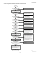


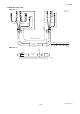
Table Of Contents
- Contents
- 1. INTRODUCTION
- 2. HANDLING PRECAUTIONS
- 3. INSTALLATION
- 4. WIRING
- 5. BASIC OPERATING PROCEDURES (USING THE DISPLAY UNIT)
- 6. PARAMETER DESCRIPTION
- 6.1 Parameters
- 6.2 Parameter Lists
- 6.3 Parameter List Overview
- 6.4 Parameter Description
- (1) Menu B: Easy Setup items
- (2) Menu C: Basic Setting items
- (3) Menu D: Total Setting items
- (4) Menu E: Pulse Setting items
- (5) Menu F: Status Functions Setting items
- (6) Menu G: Alarm Setting items
- (7) Menu H: Display Setting items
- (8) Menu J: Auxiliary Function Setting items
- (9) Menu K: Diagnostic Function Setting items
- (10) Menu M: Automatic Zero AdjustmentFunction Setting items
- (11) Menu N: Loop Test Setting items
- (12) Menu P: Parameter Protection items
- 6.5 Alarm Functions
- 7. OPERATION VIA BRAIN TERMINAL (BT200)
- 8. OPERATION VIA HART COMMUNICATOR TOOL (HART 5)
- 9. ACTUAL OPERATION
- 10. MAINTENANCE
- 11. OUTLINE
- REVISION RECORD
IM 01E20C01-01E
11-5
11. OUTLINE
Vibration Conditions:
Level of vibration in conformity with IEC 60068-2-6
(SAMA31. 1-1980)
4.9 m/s
2
G or less (frequency of 500 Hz or less)
Note: Avoid locations with much vibration (with a vibration
frequency of 500 Hz or more), which may cause
damage to the equipment.
■ ACCESSORIES
Mounting bracket: 1 set
■ MODEL AND SUFFIX CODE
AXFA11 Magnetic Flowmeter Remote Converter:
Model Suffix Code Description
AXFA11
Use
Output Signal
and
Communication
Power Supply
Electrical
Connections
Indicator
Option
Magnetic Flowmeter Remote Converter
General-Purpose Use
For AXF Remote Flowtube of size
2.5 to 2600 mm (0.1 in. to 104 in.)
4 to 20 mA DC,
BRAIN Communication
4 to 20 mA DC,
HART Communication
100 V to 240 V AC or
100 to 120 V DC
24 V AC/DC
(*1)
JIS G1/2 female
ANSI 1/2 NPT female
ISO M20 1.5 female
With Indicator
Optional code (See the Table of
Optional Specifications)
G
· · ·
· · ·
· · ·
· · · ·
-D
· · ·
· · ·
· · · ·
-E
· · ·
· · · · · · ·
1
· · · · · · · ·
2 · · · · · · · ·
-0
· · · · · ·
-2
· · · · · ·
-4
· · · · · ·
1
· · · ·
/
T03.EPS
*1: In case of power supply code 2 (24 V AC/DC), optional
code A (lighting protector) is mandatory.
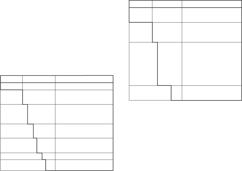
Signal Cable:
Model Suffix Code Description
AXFC
Ter mination
Cable
Length
Option
Magnetic Flowmeter
Dedicated Signal cable for the
ADMAG AXF series
No Termination. A set of termination
parts for M4 screws is attached.
Te r minated for the AXFA11/14
Converter.
Designate the cable length, unit: m
Following “L”, specify the cable in
three digits as multiple of 1 meter
(e.g., 001, 002, or 005)
for a length up to 5 m, or as
a multiple of 5 meters (i.e., 005,
010, 015, or the like).
The maximum cable length:
200 m for combined use with AXFA11
100 m for combined use with AXFA14
With termination parts sets.
Following “C”, specify the q’ty of sets
of termination parts in one digits.
·
· · ·
· ·
· · · · · · ·
-0
· · · ·
·
·
·
·
·
· ·
-4
· · ·
· ·
· ·
· ·
· ·
-L
·
·
· ·
/C
T04.EPS
Note: • The cable is constructed with double shielding
over the two conductors, and uses heat-resistant
vinyl as the outer covering material.
Finished diameter: 10.5 mm (0.413 in.)
Maximum temperature: +80˚C (+176˚F)
• Unnecessary to order the above cable for
submersible type flowtube or for the optional code
DHC flowtube because the flowtube is wired with
30 m (98 ft) cable.
• For excitation cable, prepare a two-core cable at
the customer side.