
Manual


Table Of Contents
- Contents
- 1. INTRODUCTION
- 2. HANDLING PRECAUTIONS
- 3. INSTALLATION
- 4. WIRING
- 5. BASIC OPERATING PROCEDURES (USING THE DISPLAY UNIT)
- 6. PARAMETER DESCRIPTION
- 6.1 Parameters
- 6.2 Parameter Lists
- 6.3 Parameter List Overview
- 6.4 Parameter Description
- (1) Menu B: Easy Setup items
- (2) Menu C: Basic Setting items
- (3) Menu D: Total Setting items
- (4) Menu E: Pulse Setting items
- (5) Menu F: Status Functions Setting items
- (6) Menu G: Alarm Setting items
- (7) Menu H: Display Setting items
- (8) Menu J: Auxiliary Function Setting items
- (9) Menu K: Diagnostic Function Setting items
- (10) Menu M: Automatic Zero AdjustmentFunction Setting items
- (11) Menu N: Loop Test Setting items
- (12) Menu P: Parameter Protection items
- 6.5 Alarm Functions
- 7. OPERATION VIA BRAIN TERMINAL (BT200)
- 8. OPERATION VIA HART COMMUNICATOR TOOL (HART 5)
- 9. ACTUAL OPERATION
- 10. MAINTENANCE
- 11. OUTLINE
- REVISION RECORD
IM 01E20C01-01E
3-2
3. INSTALLATION
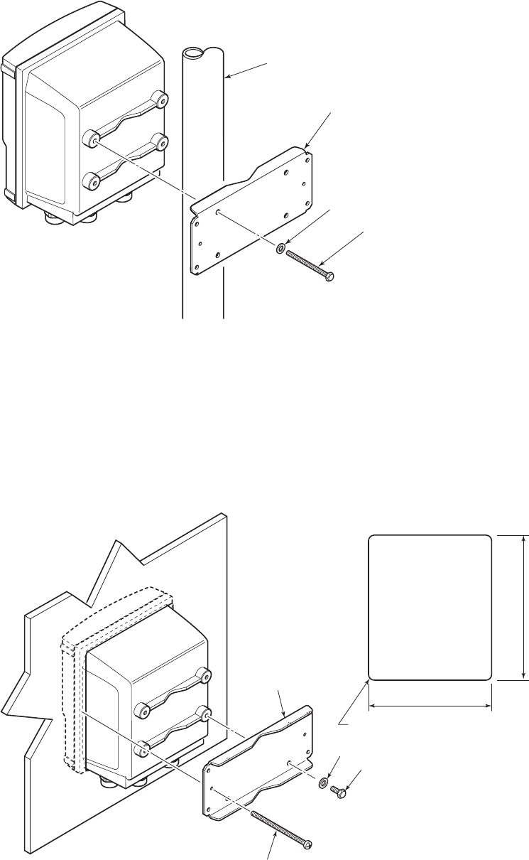
2-inch Pipe Mounting
Pass the four clamp screws through the mounting fixture, position it on the 2-inch pipe,
and then fasten the AXFA11 in place.
F0302.EPS
2-inch pipe
Mounting fixture
Washer
Clamp screw
Figure 3.2.2 2-inch Pipe Mounting
Panel Mounting
172 (6.8)
R3MAX
203 (8.0)
F0303.EPS
Fit the AXFA11 into the panel. Then attach the mounting fixture to the AXFA11 using the screw and the
washer, and secure the instrument with the two clamp screws.
Unit: mm
(approx. inch)
Mounting fixture
Panel cutout
Washer
Screw
Clamp screw
Figure 3.2.3 Panel Mounting