
User guide


13
IM 11M06D03-01E-A
VI. INSTALLATION, AUTOMATIC CALIBRATION, AC1
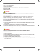
6.1LOCATION
Thefollowingguidelinesshouldbeusedwhenselectingalocationforthecalibrationunit:
1) Easily accessible for maintenance and inspections.
2) AsclosetotheZR22probeaspractical.Thiswillminimizetheamountoftubingrequiredforplumbing,and
decreasecalibrationtimes.Ambienttemperatureshouldnotexceed55˚C(131˚F).
3) Humidityismoderateandnocorrosivegasesarepresent
Use an air purge for the AC1 enclosure if the corrosive gases or high dust content is present.
4) Minimal vibration
5) Clean, dry instrument air is available
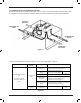
6.2MOUNTINGTHEAC1
TheAC1isavailableinaNEMAandNEMA4X,lockableenclosure,andtheunitisdesignedforwallmounting.Itcan
be secured using four (4) standoffs and four (4) bolts. Mount the AC1 unit so that the terminal strip is easily visible for
wiringpurposes.Sufcientroomshouldbemadeavailableforconnectingthecalibrationandreferencegastubing.
Theunitmustbemountedaslevelaspossibletoensuretheaccuracyoftheowrates
6.3PIPING
AlistofrecommendedpartforpipingtotheMC1andAC1unitsislistedpreviouslyinTable4.1
6.3.1PIPINGTOTHEZR22GOXYGENPROBE
6.3.2CONNECTIONTOTHECALIBRATIONGASINLET
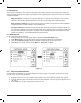
ConnectthetubingfromtheZero(cal)gasoutput,showninFigure5.1,totheCALINsideoftheZR22probe.Ifthe
processisapositivepressureapplication,ensurethatacheckvalve(YokogawaPartNumberM1234VV-A)is
installedbetweentheCALINportandthe1/4”tubing.Thecheckvalvemayalreadybeinstalledonthedetector
prior to shipping.
6.3.3CONNECTIONTOTHEREFERENCEGASINLET
ConnectthetubingfromtheReferencegasoutput,showninFigure5.1,totheREFINsideoftheZR22probe.
Clean,dryinstrumentairisrecommendedasareference(span)gas;however,ambientairmaybeusedasa
substitute.
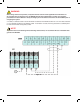
6.4.WIRINGTOTHEAC1,AUTOMATICCALIBRATIONUNIT
6.4.1WIRINGTHEAC1TOTHEZR22G
ThesolenoidsoftheAC1arepoweredby24VDCfromtheZR402GOxygenConverter.TheAC1itselfcanbe
poweredbytheZR402GiftheZR402Gisusing120VAC,60Hz.SupplyvoltagefortheAC1canbeobtainedfrom
terminals“L,N&G”ontheZR402G.PleaserefertothewiringdiagramlocatedinAppendixC.
NOTE
NOTE