
User guide


10
IM 11M06D03-01E-A
IV. INSTALLATION, MANUAL CALIBRATION (MC1)
4.1 LOCATION
Thefollowingguidelinesshouldbeusedwhenselectingalocationforthecalibrationunit:
1) Easily accessible for maintenance and inspections.
2) Locating the MC1 close to the ZR22 probe minimizes the amount of tubing required for plumbing.
Conversely, mounting the MC1 close to the ZR402G eliminates the need for two technicians to accomplish
the calibration.
3) Ambienttemperatureshouldnotexceed55˚C(131˚F).
4) Humidityismoderateandnocorrosivegasesarepresent
5) Minimal vibration
6) Clean, dry instrument air is available
4.2 MOUNTING THE MC1
TheMC1unitisdesignedforwallmounting,andcanbesecuredusingfour(4)standoffandfourbolts.Sufcient
room should be made available for connecting the calibration and reference gas tubing.
Theunitmustbemountedaslevelaspossibletoensuretheaccuracyoftheowrates
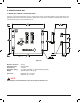
4.3 PIPING
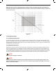
Plumbing is required from the instrument air line and zero gas cylinders to the calibration unit. Standard 1/4” Stainless
Steeltubingisrecommended.Separatetubingfortheinstrumentairandzerogasareconnectedtothe1/4”FNPT
ttingsontheLEFTsideofthecalibrationunit.Theinput/outputttingsareall1/4”FNPTttings,andareavailablein
brassorstainlesssteel.Theprobeconnections(calibrationandreference)arelocatedontheRIGHT.Seegure4.1
Never use pure nitrogen for calibration.
Compressed gas cylinders must have the same CGA connection as the dual stage regulator. Refer to the
AppendixA(SparePartssection)ofthismanualfortheDualStageRegulator(M1132ZX)andtheZero
Pressure Switch (M1133AR).
4.3.1 PIPING TO THE ZR22G OXYGEN PROBE
4.3.2 Connection to the Calibration Gas Inlet
ConnectthetubingfromtheZero(cal)gasoutput,showninFigure3.1,totheCALINsideoftheZR22probe.If
theprocessisapositivepressureapplication,ensurethatacheckvalve(YokogawaPartNumberM1234VV-A)is
installedbetweentheCALINportandthe1/4”tubing.Thecheckvalvemayalreadybeinstalledonthedetector
prior to shipping.
NOTE
NOTE
NOTE