User’s Manual MC1/AC1 Single Channel Calibration Unit For use with ZR402G IM 11M06D03-01E-A IM 11M06D03-01E-A Copyright 2007 4th Edition Feb 2013
User’s Manual I. II. III. MC1/AC1 Single Channel Calibration Unit For use with ZR402G Introduction............................................................................................4 Overview……………………………………………………………… .........4 2.1 2.2 2.2.1 2.2.2 Principles of Calibration…………………………………………………..............................4 Gases………………………………………………………………………….........................5 Span/Reference Gas…………………………………………………………........................5 Calibration Gas (Zero Gas)………………………………………………….....
IM 11M06D03-01E-A
I. INTRODUCTION There are two types of single channel calibration units offered by Yokogawa. These calibration units are used with the ZR402G Single Channel Oxygen Analyzer, to perform calibration of either ZR22G or ZO21D (obsolete) Oxygen Probes. The AC1 Automatic Calibration Unit utilizes electrical solenoids that are wired to and actuated by the ZR402G. Once activated by the ZR402G, the calibration gases flow to the ZR22 without the user opening valves or adjusting flow rates.
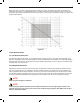
With this analyzer, the sensor (Zirconia element) is heated up to 750˚C, so Equation (2) is valid. At that point, the relationship as in Figure 2.1 is effected between the oxygen concentration of the measurement gas in contact with the positive electrode and the electromotive force of the sensor (= cell), where a comparison gas of air is used on the negative electrode side. Figure 2.1 2.2 CALIBRATION GASES 2.2.
III. SPECIFICATIONS, MC1 3.1 MODEL MC1, MANUAL CALIBRATION PANEL The MC1 is the manual calibration unit for a single oxygen probe. It provides regulation of the reference air and calibrations gas while allowing the operator to select zero or span gas for calibration. Separate flow meters are used to set cal gas flow rates and reference air. Figure 3.
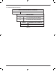
3.1.2 ORDERING SPECIFICATIONS: SINGLE CHANNEL O2 MANUAL CALIBRATION MC1 MODEL NUMBER TUBING/FITTINGS -C 1/4” Copper Tubing and Brass Fittings -S 1/4” Stainless Steel Tubing and Fittings CODE B REFERENCE AIR FLOW METER -R*U Reference Air Flow meter Table 3.
3.2. SPECIFICATIONS, AC1 3.2.1 MODEL AC1, SINGLE POINT AUTOMATIC CALIBRATION UNIT The AC1 provides control of reference air and cal gas flow rates while maintaining a constant regulation of gases. The AC1 includes individual span, zero and block solenoids with manual overrides for easy setup of flow rates. The user has a choice of copper or stainless steel tubing in addition to NEMA 4 or NEMA 4X enclosures. . It also contains a 1 amp fuse with an LED indicator to indicate a power surge. Figure 3.
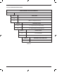
3.2.2 AC1 ORDERING SPECIFICATIONS SINGLE CHANNEL O2 AUTO CALIBRATION AC1 MODEL NUMBER CODE A ENCLOSURE -4 NEMA 4, Metal Enclosure -5 NEMA 4X, Fiberglass Enclosure CODE B TUBINGS/FITTINGS -C 1/4” copper Tubing and Brass Fittings -S 1/4” Stainless Steel Tubing and Fittings CODE C POWER SUPPLY -A For use with ZA8C -D For use with ZR402G (requires 110 VAC) CODE D REFERENCE AIR CONNECTION -R*U Reference Air Connection Table 3.
IV. INSTALLATION, MANUAL CALIBRATION (MC1) 4.1 LOCATION The following guidelines should be used when selecting a location for the calibration unit: 1) 2) 3) 4) 5) 6) Easily accessible for maintenance and inspections. Locating the MC1 close to the ZR22 probe minimizes the amount of tubing required for plumbing. Conversely, mounting the MC1 close to the ZR402G eliminates the need for two technicians to accomplish the calibration. Ambient temperature should not exceed 55˚C (131˚F).
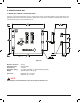
4.3.3 CONNECTION TO THE REFERENCE GAS INLET Connect the tubing from the Reference gas output, shown in Figure 4.3, to the REF IN side of the ZR22 probe. Clean, dry instrument air is recommended as a reference (span) gas; however, ambient air may be used as a substitute. ZERO (CAL) GAS INPUT INSTRUMENT AIR INPUT REFERENCE AIR OUTPUT CALIBRATION GAS OUTPUT Figure 4.1 A list of recommended part for piping to the MC1 or AC1 units is listed below in Table 3.
V. SETUP PROCEDURES, MC1 5.1 INITIAL FLOW RATE SETUP Locate the reference air flow meters, and adjust the flow adjustment knobs as outlined below: Reference Air: 0.8 LPM Calibration Gas: 0.6 LPM CAUTION The maximum working pressure of the MC1 and AC1 unit is 35 psi. Excessive pressure can damage the Zirconia cell of the ZR22G Oxygen Probe. 5.
VI. INSTALLATION, AUTOMATIC CALIBRATION, AC1 6.1 LOCATION The following guidelines should be used when selecting a location for the calibration unit: 1) Easily accessible for maintenance and inspections. 2) As close to the ZR22 probe as practical. This will minimize the amount of tubing required for plumbing, and decrease calibration times. Ambient temperature should not exceed 55˚C (131˚F).
WARNING When wiring electrical components, verify that electrical current and all applicable circuit breakers are de-energized prior to wiring the AC1 and ZR402G. Ensure that all applicable “Lock Out” and “Tagging” procedures have been adhered to. Verify the integrity of ALL electrical connections and terminations prior to energizing the system. A 16 AWG, 4 conductor cable is recommended for use between the ZR402G and the AC1 Unit. The cable should be run in a separate conduit from the detector cables.
VII. SETUP PROCEDURES, AC1 Locate the reference air flow meters, and adjust the flow adjustment knobs as outlined below: Reference Air: 0.8 LPM Calibration Gas: 0.6 LPM CAUTION The maximum working pressure of the MC1 and AC1 unit is 35 psi. Excessive pressure can damage the Zirconia cell of the ZR22G Oxygen Probe. 7.1 INITIAL FLOW RATE SETUP Ensure that the calibration gas and reference air lines are properly plumbed to the left side of the AC1 Auto Cal Unit.
7.3 CHECKING FOR LEAKS NOTE To prevent leakage, all threaded connections should have Teflon tape (or suitable alternative) and all compression fittings should be installed per manufacturer’s recommendations. 1. Locate the BLOCK SOLENOID. Turn the override screw on the BLOCK SOLENOID and SPAN SOLENOID to the manual position. 2. Use leak detection spray on all compression fittings and bends of the cal and reference line tubing. 3. Inspect the full length of the tubing to determine if there is a leak. 4.
VIII. CALIBRATION SETUP & OPERATION, ZR402G 8.1 ZR402G TOUCH PANEL SWITCH OPERATIONS The converter uses a touch panel switch which can be operated by just touching the panel display. Figure 8.1 shows the basic panel display. The switches that appear in the switch display area vary depending on the panel display, allowing all switch operations. Figure 8.2 shows the switch functions. FIGURE: 8.
8.2 CALIBRATION The converter is calibrated in such a way that the actual zero and span gases are measured and those measured values are used to agree with the oxygen concentrations in the respective gases. There are three types of calibration procedures available: Manual calibration: conducting zero and span calibrations, or either of these calibrations in turn. Manual calibration needs the MC1 Manual Calibration Unit to allow manual supply of the calibration gases.
8.2.3 SPAN-GAS CONCENTRATION Set the oxygen concentration for span calibration. If instrument air is used as the span gas, enter 21 %O2. 1) Select Span gas conc. from the Calibration setup display. 2) Enter the desired span-gas oxygen concentration from the numeric-data entry display. (The span-gas set ranges from 4.5 to 100 %O2.) 3) Enter 02100 for an oxygen concentration of 21 vol%O2.Instrument air is here defined as dry air with a dew-point temperature of no higher than -208˚C.
To start calibration using an input contact, follow these steps: (1) Make sure that Calibration start has been selected in the Input contacts display (2) Apply an input contact to start calibration. To stop calibration midway, follow these steps: (1) Press the Return key. If this key is pressed midway during calibration, the calibration will stop and the output stabilization time will be set up.
APPENDIX A SPARE PART IM 11M06D03-01E-A
MODEL MC1 1. 2. 3.
MODEL AC1 1. 2. 3. 4. M1132YX M1132PF M1132PB M1132CC M1132ZC 5.
Zero Gas Regulator, M1132ZX This regulator controls the gas pressure of the zero gas cylinders before it reaches the calibration unit. The dual stage regulator is highly recommended for services which require a near constant delivery pressure as the calibration source decays (See M1133AR). Air diffusion and absorption, desorption and off gassing are minimized because of its stainless steel construction. NOTE This regulator is used on a “zero gas” cylinder with a CGA 580 connection.
Zero Pressure Switch, M1133AR The pressure switch is used to alert the Operator via a contact input that the zero gas cylinder needs to be replaced before the cylinder is empty. The recommended connection is to the high pressure side of the zero gas regulator. Refer to Figure 4.1.
APPENDIX B DIMINSIONAL DRAWINGS IM 11M06D03-01E-A
MC1 MC1 IM 11M06D03-01E-A
AC1-4 NEMA 4 AC1-4, with NEMA 4 Enclosure IM 11M06D03-01E-A
AC1-5, NEMA 4X AC1-5, with NEMA 4X Enclosure IM 11M06D03-01E-A
APPENDIX C WIRING DIAGRAM IM 11M06D03-01E-A
IM 11M06D03-01E-A
IM 11M06D03-01E-A