
Manual


50 Installation
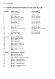
7.2 WIRING DESIGNATIONS FOR THE 414D & 414B
Terminal Model 414D Model 414B
1 Calibration Link Calibration Link
2 Signal Ground Signal Ground
3 Not To Be Used Not To Be Used
4 Remote Display Switch Not To Be Used
5 Remote Batch Set Switch Not To Be Used
6 Not To Be Used Not To Be Used
7 Flow Alarm Not To Be Used
8 Flow Common (-) Flow Common (-)
9 Flow Pulse Input Flow Pulse Input
10 Pulse Out Not To Be Used
11 DC Power Out (8-24 VDC) DC Power Out (8-24 VDC)
12 DC Ground DC Ground
13 DC Power Input DC Power Input
14 Not To Be Used Not To Be Used
Terminal RS232/422/485 Option
20 RS232 Signal Ground
21 RS232 Data In
22 RS232 Data Out
23 RS422/485 (-) Data Out
24 RS422/485 (+) Data Out
25 RS422/485 (-) Data In
26 RS422/485 (+) Data In
27 RS232 CTS
Terminal Relay Output & Switches
28 Remote RUN Switch
29 Remote STOP Switch
30 End of Batch/Pump Control Signal
31 Relay 2 - Normally Open
32 Relay 2 - Normally Closed
33 Relay 2 - Common
34 Relay 1 - Normally Open
35 Relay 1 - Normally Closed
36 Relay 1 - Common