BATCH CONTROLLERS MODELS 414D & 414B July 2001
CONTENTS 1. Introduction 1.1 Model Number Designation 3 5 2. Specification 6 3. Operation 8 3.1 Front Panel Operation 3.2 Batch Operations 3.2.1 Control Relay Outputs 3.2.2 Signal Timeout 3.2.3 End of Batch 3.2.4 Auto Restart 3.2.5 Automatic Overrun Compensation 3.3 Calculation of Rate and Total 3.3.1 Frequency Input 3.3.2 Filtering 3.4 Total Conversion 3.5 The Output Pulse and Flow Alarm (Model 414D Only) 4. Options 4.1 The RS232/422/485 Interface Option 4.1.1 Hardware 4.1.
6. Input Circuits 6.1 Input Circuit for the Model 414D 6.2 Input Circuit for the Model 414B 6.3 Remote Switches 7. Installation 7.1 General 7.2 Wiring Designations for the 414D & 414B 7.3 Ex 410 Enclosure Dimensions 8. Trouble Shooting 8.
Introduction 3 1. INTRODUCTION The Models 414D and 414B Batch Controllers accept pulse or frequency flow signals and automatically control the batching of fluids via a one or two stage control valve. The instruments are extremely flexible and easy to operate, with a four key, front panel operation that enables the batch quantity to be set, and batches to be started or stopped. This manual covers both the Model 414D and 414B.
4 Introduction Generic Immunity Standard EN 50082-1 Residential, Commercial & Light Industry Environment. Generic Immunity Standard EN 50082-2 Industrial Environment. In order to comply with these standards, the wiring instructions in Section 8.1 must be followed.
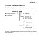
Introduction 5 1.1 MODEL NUMBER DESIGNATION The Model number of an instrument describes which input and output options are installed and the AC mains voltage rating. Model 414 D .
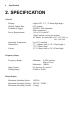
6 Specification 2. SPECIFICATION General Display: Display Update Rate: Transducer Supply: Power Requirements: Operating Temperature: Dimensions: Cutout: 6 digit LCD. 0.7" (17.8mm) high digits. 0.25 seconds. 8-24VDC field adjustable. 50mA maximum. 11.5 to 28.5 volts DC. 130mA typical current (no options). AC Mains: Set internally to 95 - 135 VAC or 190 - 260 VAC. 0 to 55°C standard. 5.7" (144mm) wide x 2.8" (72mm) high x 7.0" (178mm) deep. 5.5" (139mm) wide x 2.6" (67mm) high.
Specification Pulse Output (Model 414D Only) Pulse Width: Maximum Duty Cycle: Scaling: 10mSec (negative going pulse). 49 pulses per second. The pulse output is scaled and outputs one pulse each time the accumulated total increments.
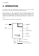
8 Operation 3. OPERATION The Models 414D and 414B Batch Controllers use a low power CMOS microprocessor to perform all control functions and calculations. Both instruments are fully programmable with all operating parameters and calculation constants user programmable. (See Section 5 entitled "Calibration" for information on programming.) All parameters and constants are stored in a nonvolatile memory which retains data without battery backup for a minimum of 10 years.
Operation 9 3.1 FRONT PANEL OPERATION The four key operation of the Batch Controller is straightforward. SETTING THE BATCH QUANTITY The Batch quantity is programmed as follows: Switch Action Display Comments Press BATCH SET Batch "Batch" is displayed for one second followed by the batch quantity last entered. The Batch Set LED lights. "1" 2345 The most significant digit flashes indicating that it can be changed. Press < "2" 2345 Pressing the DISPLAY key will increment the digit.
10 Operation The Batch quantity can only be set while the instrument is in non-operational state such as when the batch is complete, or if the batch process has been interrupted. However, the Batch key can be pressed while in the run state and the Batch quantity checked. All digits will flash to signal the quantity cannot be changed. STARTING A BATCH To start the process the RUN key is pressed.
Operation 11 DISPLAYED INFORMATION The display will normally show the Batch Total, which is the total count for the current batch and is reset on each new batch. The DISPLAY key can be used to display the following additional information: Rate On the first press of the DISPLAY key, the display shows RATE for one second followed by the flowrate. Accumulated Total On the next press of the DISPLAY key, the display shows ACC for one second followed by the actual total.
12 Operation 3.2 BATCH OPERATIONS The Batch Control functions can be programmed, during Calibration, to operate in one of two ways. 1. At the end of the batch, the STOP key must be pressed to reset the Batch Total. (This must be done before another batch can be started.
Operation 2. 13 If Automatic Reset is programmed, a new batch is commenced each time the RUN key is pressed. PAUSE Run Stop Run Batch Quantity Reached Run Count Down Count Up Relay 1 Relay 2 Start Time End of Batch Prestop Quantity Auto Restart Time End of Batch The Batch Controller can also be programmed, during Calibration, to either count up from zero on each batch, or to count down from the preset batch quantity.
14 Operation 3.2.1 Control Relay Outputs The two output relays can be set up to control a single valve or a dual valve with slow stop and/or slow start. Alternatively, the second relay can be used to control a pump. The relay operation is shown on the previous two pages. A time delay between the Start and the time when relay 2 energises can be programmed to provide a soft startup. The delay can range from 0 (no delay) to 79 minutes and 59 seconds. A Prestop quantity (ie.
Operation 15 3.2.2 Signal Timeout The Signal Timeout period defines a time interval which is used to detect if the flow has stopped. If there is no signal input for a time greater than the Signal Timeout period, the flow is deemed to have stopped. A Signal Timeout period has two functions: ♦ To detect the loss of signal midway through a batch when the relays are energised. In this case, the Batcher will enter a Flow Alarm condition and de-energise the relays.
16 Operation 3.2.3 End of Batch An End of Batch is defined as being when the Batch Quantity is reached, the flow has stopped and the Signal Timeout period has expired. If the Signal Timeout is set to zero, the End of Batch is defined as being when the Batch Quantity is reached, regardless of whether the flow has stopped. The Batch Controller cannot be reset or restarted until the End of Batch and similarly, for an RS232/422/485 interface, data will not be output until the End of Batch has been determined.
Operation 17 3.2.4 Auto Restart The Batch Controller can be programmed to continually repeat the batch process. This mode of operation is selected during the programming procedure. The process is started by pressing the RUN key whereby the normal batch operation is commenced. After reaching the End of Batch (see Section 3.2.3), the Batch Controller will then wait for a pre-programmed period before automatically resetting and starting the batch process once again.
18 Operation 3.2.5 Automatic Overrun Compensation The Batch Controller can be programmed to automatically compensate for any overrun at the end of a batch. Typically, this could be due to the slowness of a valve to close or a pump to stop pumping on receiving a signal from the Batch Controller. The result is that the batch quantity will always read higher than the batch quantity set.
Operation 19 3.3 CALCULATION OF RATE AND TOTAL 3.3.1 Frequency Input The flowrate, R, is calculated as follows: R = f xH S where f is the input frequency in Hz. H is the timebase of rate and is 1 for seconds, 60 for minutes, 3600 for hours and 86,400 for days. S is the Scaling Factor. The Scaling Factor, S, is equal to the K-factor of the flowmeter expressed in pulses per unit volume.
20 Operation 3.3.2 Filtering Frequency fluctuations caused by pulsating flow through a flowmeter, often makes the Rate impossible to read with any precision. The Batch Controller has a digital filter which will average out these fluctuations and enable the Rate to be read to four digit accuracy. The ability to select a suitable filtering level means that highly accurate and stable readings can be obtained without excessive lag.
Operation A 90% 99% 1 2 4 6 10 15 20 25 35 45 60 75 90 99 0 1 2 3 5 8 11 14 20 25 34 43 52 57 0 2 4 6 11 17 22 28 40 51 69 86 103 113 Table 1 - Response to a step Input (in seconds). Note that if A is set to 1 there is no filtering of the input signal.
22 Operation 3.4 TOTAL CONVERSION The Total Conversion feature enables the rate to be displayed in one engineering unit (eg. gallons/minute) and the totals to be displayed in another engineering unit (eg. barrels). The Scaling Factor is always programmed in the unit relating to Rate, and the Total Conversion constant is a division factor which can be used to convert the totals to the different unit. The Total Conversion factor affects the net, accumulated and gross totals and is limited between 0.
Operation 23 3.5 THE OUTPUT PULSE AND FLOW ALARM (Model 414D Only) An OUTPUT PULSE is available on terminal 10 for driving remote counters and produces a pulse each time the Accumulated Total increments by one digit. For example, if the Accumulated Total has a resolution of 0.01 litres, a pulse is produced each 0.01 litres. The pulse is a current sinking pulse of approximately 10mSec produced by an open collector transistor.
24 Operation Connection of Output Pulse and Flow Alarm are as follows: Relay or Impulse Counter 5.6 ohms 33V Zener 12 DC Supply Driving an External Relay or Impulse Counter DC Supply Out (8-24V) 11 External Load Resistor 10K Logic Input 5.
Options 25 4. OPTIONS 4.1 THE RS232/422/485 INTERFACE OPTION With this option installed, the circuits for both the RS232 and RS422/485 are provided as standard. They can be used to interface to both printers and computers and a number of standard protocols are built into the instrument. 4.1.1 Hardware The following diagram provides an overview of the RS232/RS422/RS485 communications hardware.
26 Options 4.1.2 Multipoint Communication Multipoint Communication is a system whereby a number of instruments can be addressed over a dual twisted pair interface. Up to 32 instruments can be connected to a common bus using the RS422 and RS485 interfaces as shown below. To convert the RS422 interface to an RS485 interface, the RS422 (-) Data In Terminal must be connected to the RS422 (-) Data Out Terminal and the RS422 (+) Data In Terminal must be connected to the RS422 (+) Data Out Terminal.
Options 27 Twisted Pair + Host Computer Load 120 ohms Gnd - In + Gnd - + Out 400 Series Instrument - In + Gnd - + Out 400 Series Instrument Figure 2 RS485 Interface
28 Options 4.1.3 Communication Protocol The Model 414D/B has a real time clock and enables the time and date to be set and printed on tickets. The date format can be European (days/months/years) or USA (months/days/years), while the time is on a 24 hour clock. Note that the clock will only retain its time for 3 days minimum if there is no power connected to the instrument. After this period, the clock may need to be reset.
Options 29 A CTS input is provided, and will prevent the instrument from transmitting any further characters to a printer if the printer buffer is full. The CTS input is usually connected to the "Data Buffer Full" output from the printer. If the printer buffer is large enough to handle the messages output from the Batch Controller, then this input need not be used and can be left unconnected.
30 Calibration 5. CALIBRATION The Calibration routine enables the Setup Parameters to be programmed, as well as enabling the input signals to be checked. The calibration routine can be entered in two ways: 1. By connecting a wire link (or switch) to the rear terminal strip across terminals 1 and 2 or, 2. By pressing the STOP key and while still holding, press the DISPLAY key. Both keys must then be held for approximately 6 seconds.
Calibration 31 On first entering the Calibration routine, the display will show: CAL Batch Option Test End Setup Program parameters (see Section 5.1) Enter Batch parameters (see Section 5.2) Option - if installed (see Section 5.3) Check Input Signals (see Section 5.4) Exit to Normal Operation The user can toggle between these modes using the DISPLAY switch and by using the STOP switch, select the appropriate mode.
32 Calibration 5.1 PROGRAMMING THE SETUP PARAMETERS Step 1 Display Description CAL Select the Calibrate mode to setup program parameters. Select Batch to enter Batch Setup parameters. Option (if installed). Select the test mode to check input signals. Exit to normal operation. BATCH OPTION TEST END Text Ref 5.2 5.3 5.4 The following steps are displayed if CAL is selected. 2 RESTOT Reset all totals to zero. To reset all totals (resettable and accumulated) press the BATCH SET key once.
Calibration Step 7 Display Description TOTCON A division factor to convert the totals to different units from those used for rate (ie.gallons/min and barrels). 1 Rate and totals have the same engineering units. x.xxxx Other factors can be programmed between 0.01 and 2000. 8 t.dPt Number of decimal points with which the resettable total is displayed between 0 to 0.000. 9 A.dPt Number of decimal points with which the Accumulated (non resettable) total is displayed between 0 to 0.000.
34 Calibration 5.2 ENTERING THE BATCH PARAMETERS Step 1 Display Description BATCH OPTION TEST END CAL Enter Batch Parameters. Option (if installed) Check Input Signals. Exit to normal operation. Program Setup Parameters. Text Ref 5.3 5.4 5.1 The following steps are displayed if BATCH is selected. 2 BATCH L xxxxxx Maximum Batch Size which can be entered. Set to 0 if no limit on batch size. 3 AUTO S Automatic restart feature. Off On xx:xx Disable. Enable.
Calibration Step 6 7 8 9 Display Description COUNT The Batch Total counts Up or Down. dn up Count down from the batch quantity. Count up from zero. T OUT The Signal Timeout in seconds. (Setting to 00 disables this feature.) 35 Text Ref 3.2 3.2.2 AOC Automatic Overrun Compensation. Note that the Signal Timeout must be greater 3.2.5 than 0 (ie. enabled) for this feature to work. En Dis Enable. Disable. AUTO R Auto Reset (not displayed if Auto Restart is programmed - Step 3 above).
36 Calibration 5.3 PROGRAMMING OPTIONS Step 1 Display Description OPTIONS Test End CAL Batch Options (if installed). Check the Input Signals. Exit to normal operation. Program Setup Parameters. Set Batch Parameters. Text Ref 5.4 5.1 5.2 If the RS232/422/485 option is installed, the following will be displayed: 2 DF Eur USA Date Format. European (ie. days/months/years). USA (ie. months/days/years). 4.1 3 Date xx:xx:xx Enter date as: Years:Months:Days. 4.
Calibration Step Display Description 9 ID NO 0 1 - 99 Unit Identification Number. None. Id number. 10 P TYPE xx Printer/Computer Type. 00 01 02 03 04 05 Standard Computer Printer. EPSON CTM 290 Slip Printer. Contrec Model 624 Printer. EPSON TM 290-2 Slip Printer. Contrec Model 632-2 Printer. Syntest SP-210 Printer. 20 Computer. Text Ref If a Printer Protocol is selected, the following message is displayed: 10 UNIT xx Units of measurement printed. 00 01 02 03 04 05 06 07 None.
38 Calibration 5.4 CHECKING THE INPUT SIGNAL Step 1 Display Description TEST OPTIONS CAL BATCH END Check the Input Signals. Options (if installed). Program Setup Parameters. Set Batch Parameters. Exit to normal operation. Text Ref The following steps are displayed if TEST is selected. 2 Sr x.xx Software revision number. 3 Freq Displayed for 1 second followed by the actual frequency. Frequency in Hz. xxxx.
Input Circuits 39 6. INPUT CIRCUITS This section covers the connection of flowmeter signals for: ♦ Model 414D Batch Controller with input signal conditioning card. ♦ Model 414B Batch Controller with a basic signal input capability. Both the Model 414D and 414B have a regulated output which can be used to power sensors. A trimpot on the rear of the instrument allows the voltage to be adjusted in the range of 8-24 Volts and the output can supply a maximum of 50mA. 6.
40 Input Circuits Switch Settings The following switch settings are recommended for different input signal types. Input Signal Type Input Terminals Switch Settings CH1 a. Logic Signal, CMOS, Pulse b. Open Collector or Reed switch c. Namur Proximity (set DC out to 8 volts) d. Switch or Reed Switch with debounce circuit (200Hz max) e. Coil (20mV P-P minimum) f.
Input Circuits +5V 10K Pulse Input (9) S1 100K Common + S8 S3 2K4 (8) INPUT COMPARATOR S7 1K 100R .
42 Input Circuits 1. Squarewave, CMOS or Pulse on 9 Common 8 Model 414D 8 1 eg. vortex, preamplifiers or magnetic flowmeters 2. Open-Collector on 9 Common 8 Model 414D 8 1 eg. hall effect sensors 3. Reed Switch on Model 414D 9 1 8 8 eg.
Input Circuits 4. Coils on 9 Model 414D 8 1 8 Use shielded cable to case earth eg. millivolt signal from a turbine flowmeter (single input only) 5. Namur Proximity Switch on +8V 11 9 Model 414D 8 1 eg. positive displacement flowmeters with 2 wire proximity switch outputs 6. Opto-Sensors Resistor on 1 9 Common Model 414D 11 8 8 eg. preamplifiers and opto-sensors Note that the current limiting resistor may be required. See the flowmeter manufacturer's data.
44 Input Circuits 6.2 INPUT CIRCUIT FOR THE MODEL 414B The Model 414B will accept basic squarewave, pulse or open collector output signals, but is not able to read mV signals from coils, nor two wire proximity switch outputs. The Model 414B has limited input filtering and signal levels must switch between the levels specified below. For open collector outputs, an internal 10K resistor will act as a load. However, the user must still ensure that the resulting signal will switch about the specified levels.
Input Circuits The Input Circuit 5V Model 414B 10K Pulse Input 9 1K .01 Signal 8 Ground 1. Squarewave or Pulse Inputs Model 414B 9 Common 8 eg. vortex or magnetic flowmeters 2. Open-Collector Inputs Model 414B 9 Common 8 eg.
46 Input Circuits 3. Opto-Sensors Resistor 11 9 Common 8 Model 414B Note that the current limiting resistor may be required. See the flowmeter manufacturer's data. 4. Reed Switch 9 8 Model 414B eg.
Input Circuits 47 6.3 REMOTE SWITCHES Remote push-buttons can be connected to the Models 414D and 414B to duplicate the switches on the front panel. On the Model 414D, all four switches are taken to the rear terminals, while only the RUN and STOP switches are available on the Model 414B.
48 Installation 7. INSTALLATION 7.1 GENERAL Terminal designations for the Model 414Dand 414B Batch Controllers are given on the following pages. The cutout hole in the panel should be 5.5" (139mm) wide x 2.6" (67mm) high. Two side clips are supplied to secure the instruments into panel. A case earthing point is provided via an earth lug on the side of the case. Note that this earthing point is for the case only and there is complete electrical isolation between this point and all electronic circuits.
Installation 49 It is good practice to use shielded cable for all signal connections to the Model 414. Care must be taken to separate signal cables from power cables so as to minimise interference. Overall shields should be connected to the case earth at the instrument end only. This connection should be as short as possible and connected to the earthing lug on the side of the case.
50 Installation 7.
Installation 51 7.3 EX 410 ENCLOSURE DIMENSIONS (all dimensions in mm) Mounting Holes (4) on rear Metric thread M8 NPT thread 5/16 UNF Ex 410 Enclosure with 5 Keys Door Hinge 115.0 288 221 302 Bottom View Mounting Holes 4 x 5/16 UNF Mounting Holes 4 x M8 Earth Point 130.0 70.0 70.0 71.5 71.5 Gland Holes 3 x M20 Enclosure with 3 x M25 Gland holes Material: Cast Aluminium Finish: Light beige powdercoat 130.
52 Trouble Shooting 8. TROUBLE SHOOTING Batcher does not reset. The Signal Timeout has been set to an excessively long period and has not timed out at the end of the last batch. Batch will not start or relay 1 will not close. Ensure that the instrument has not timed out as controlled by the Signal Timeout and that a Flow Alarm condition does not prevail. Pressing the Stop switch will cancel this condition. Check for a fault on the flow input before restarting. Batcher stops midway through a batch.
Trouble Shooting 53 Not counting. If the Batcher does not count with the flowmeter connected and flow passing through it, first check the connections and then ensure the DIL switches (Model 414D only) on the rear of the instrument are set as per Section 6. It is possible to manually test the input circuit of the Batcher by setting the input configuration for a Reed Switch (see Section 6) and pulsing across the signal (+) and (-) with a wire link.
54 Trouble Shooting No end of batch, pulse output or flow alarm. This fault is usually caused by lack of a pullup resistor or load on the output. The outputs themselves have no internal pullups and rely on an external load.
Trouble Shooting 55 8.1 ERROR CODES The instrument has extensive self test facilities and will display an error code if it detects an invalid condition. If the instrument displays an error code other than those listed below, please contact the factory. Error codes are displayed as "Err 12" and a list of commonly encountered codes are given below: Error Codes Input Errors 11 13 14 Invalid input configuration programmed. Signal Timeout (see Section 3.2.2).
56 Index Index A Access, 33 Accumulated Total, 11 Auto Reset, 10 Auto Restart, 17 Automatic Overrun Compensation, 18 B Backlite, 5 Batch Limit, 11 Batch Set, 9 Battery Backup, 8 Baudrate, 28 C Calibration, 30 Communication Protocol, 28 Computer, 29 Conformal Coating, 5 Control Functions, 12 Control Relay, 14 Count Down, 10 Count Up, 10 Cutout, 6 E Earth Lug, 48 Earthing Point, 48 End of Batch, 16 Error Codes, 55 Ex 410 Enclosure, 51 Multipoint Communication, 26 N Namur Sensors, 39 Non-volatile Memory
Index Setting the Batch, 9 Setup Parameters, 3 Signal Timeout, 15 Slow Start, 14 Slow Stop, 14 Specification, 6 Starting, 10 Stop Key, 14 Stopping, 10 Switch Settings, 40 Switching Current, 6 Switching Power, 6 Switching Threshold, 40 T Terminal, 50 Ticket, 28 Time Clock, 28 Time Delay, 14 Timebase, 19 Total Conversion, 22 Transducer Supply, 6 Trouble Shooting, 52 Turbine Flowmeters, 39 W Wiring Designations, 50 57