
User Manual


<2. WIRING AND INSTALLATION>
2-4
IM 12A01A02-01E 5th Edition : Oct. 31, 2013-00
CAUTION
Wheninstallingcableglands,holdcableglandsandtightencableglandnutstoatorqueof6
N•m. If cable glands, not gland nuts, are tightened, O-rings may be come out from the proper
positions.
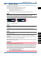
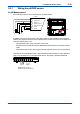
l Adapter for conduit work
Whenprotectingthecablewithaconduit,useanadapter(optioncodes:/CB4,/CD4,or/CF4).
Settheadapterasshowningure2.5,insteadofusingthecableglandasshowningure2.4.
Adapter
49
(1.93")
G1/2 screw (/CB4), 1/2 NPT screw (/CD4)
M20x1.5 screw (/CF4)
Approx.
55(2.2")
Packing
Unit: mm(inch)
Nut
F0204.ai
Figure2.5 Adapter for conduit work (option)
CAUTION
Whenusingacableconduit,useaexibleconduittoavoidstressontheconduitadapter.
The stress on the conduit adapter may damage the housing.
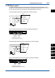
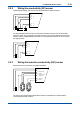
2.4 Wiring the power supply
Firstmakesurethatthepowersupplyisinaccordancewiththegivenspecications.
PowerSupply: Nominal24VDClooppoweredsystem
One(1)Sensormodule(1input): 16to40VDC(forpH/ORP,SCandDO),
17to40VDC(forISC),21to40VDC(forSENCOM)
Two(2)Sensormodules(2inputs): 22.8to40VDC(forpH/ORP,SCandDO)
Note: WhentheFLXA21isusedinthemulti-dropmodeofHARTcommunication,theoutputsignalischangedfrom12.5mADCto
4mADCjustafterthepoweristurnedon.Enoughpowersupplyfortheinstrumentsistobeprovided.
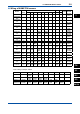
250
600
1000
0
24.718
V - 11.5
0.022
R =
1295
1617 22.8
4040
Voltage (V)
2-sensor measurement
Load resistance (Ω)
Digital Communication
Range (HART)
250
304
600
516
1000
0
24.7
18
V - 11.5
0.022
R =
1295
17
40
22.86
40
Except SENCOM
Voltage (V)
Load resistance (Ω)
Digital Communication
Range (HART)
18.2
21
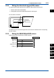
Figure2.6 Supply Voltage and Load Resistance
Open the front panel and remove the wiring covers to make the terminal block accessible.