
User Manual

<1. INTRODUCTION AND GENERAL DESCRIPTION>
1-13
IM 12A01A02-01E 5th Edition : Oct. 31, 2013-00
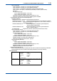
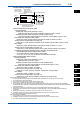
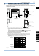
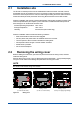
Control Drawing (CSA type)
Measuring module 1
Measuring module 2
(Refer to Note 7)
Sensor 1
Sensor 2
Housing Assembly
Supply
-
Supply
+
→
Non Hazardous Location
Hazardous Location ←
(*1)
Refer to Note
Safety Barrier
-
+
Intrinsically Safe
Group IIC, Zone 0
Class I, Division 1
Non-incendive
Class I, Division 2,
Groups A, B, C, D
2 wire analyzer
Not use safety barrier but
CSA certified equipment
use in Non-incendive
Note: The measuring module on this
drawing means the sensor module
on this General Specifications.
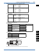
Electrical parameters (Intrinsically safe)
Housing Assembly
Supply and output circuit (terminals + and -)
Ui(Vmax)=30V,Ii(Imax)=100mA,Pi(Pmax)=0.75W,Ci=13nF,Li=0mH
Measuringmoduleinputcircuit(CN2orCN3onBackboard)
Uo(Vt,Voc)=13.65V,Io(It,Isc)=50mA,Po=0.372W,Co(Ca)=80nF,Lo(La)=7.7mH
pHmodule,SCmoduleandDOmodule
Ui(Vmax)=13.92V,Ii(Imax)=50mA,Pi(Pmax)=0.374W,Ci=40nF,Li=2.9mH
Sensor input circuit (terminals 11 through 19)
Uo(Vt,Voc)=11.76V,Io(It,Isc)=116.5mA,Po=0.3424W,Co(Ca)=100nF,Lo(La)=1.7mH
ISC module
Ui(Vmax)=13.92V,Ii(Imax)=50mA,Pi(Pmax)=0.374W,Ci=40nF,Li=7.7mH
Sensor input circuit (terminals 11 through 17)
Uo(Vt,Voc)=11.76V,Io(It,Isc)=60.6mA,Po=0.178W,Co(Ca)=100nF,Lo(La)=8mH
Installationrequirementsbetweenhousingassemblyandsafetybarrier
Uo≤UiIo≤IiPo≤PiCo≥Ci+CcableLo≥Li+Lcable
Voc≤VmaxIsc≤ImaxCa≥Ci+CcableLa≥Li+Lcable
Uo,Io,Po,Co,Lo,Voc,Isc,CaandLaareparametersofbarrier.
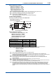
ElectricalParameters(Nonincendive)
Housing Assembly
Supply and output circuit (terminals + and -)
Ui(Vmax)=30V,Ci=13nF,Li=0mH
Measuringmoduleinputcircuit(CN2orCN3onBackboard)
Uo(Vt,Voc)=13.65V,Io(It,Isc)=50mA,Co(Ca)=80nF,Lo(La)=7.7mH
pHmodule,SCmoduleandDOmodule
Ui(Vmax)=13.92V,Ci=40nF,Li=2.9mH
Sensor input circuit (terminals 11 through 19)
Uo(Vt,Voc)=11.76V,Io(It,Isc)=116.5mA,Co(Ca)=4uF,Lo(La)=4.5mH
ISC module
Ui(Vmax)=13.92V,Ci=40nF,Li=7.7mH
Sensor input circuit (terminals 11 through 17)
Uo(Vt,Voc)=11.76V,Io(It,Isc)=60.6mA,Co(Ca)=4uF,Lo(La)=19mH
NoteforIntrinsicallySafeInstallation:
1: Inanysafetybarrierused,theoutputcurrentmustbelimitedbyaresistor“R”suchthatIo=Uo/RorIsc=Voc/R.
2: ThesafetybarriermustbeCSAcertied.
3: Inputvoltageofthesafetybarriermustbelessthan250Vrms/Vdc
4: Whenusingnonisolationbarrierconnect(*1)toISearthingsystem.
5: pHandSCSensor(s)areofapassivetypetoberegardedas‘simpleapparatus’sameas06ATEX0218X,06ATEX0219,
IECExKEM06.0052X,FM3028779,06ATEX0220X,06ATEX0221,IECExKEM06.0053Xortheoneindividuallycertiedwith
relevant parameters.
6: ISCSensor(s)areISC40Sof00ATEX1067Xortheoneindividuallycertiedwithrelevantparameters.
7: DOSensor(s)areofapassivetypetoberegardedas‘simpleapparatus’ortheoneindividuallycertiedwithrelevant
parameters.
8: Measuring module 2 may not mounted. As for ISC module, only one can be mounted.
9: Installation should be in accordance with Canadian Electrical Code Part I and Local Electrical Code.
10: DonotalterdrawingwithoutauthorizationfromCSA.
NoteforNonincendiveInstallation:
1: The parameter for sensor input circuit must be taken into account when installed.
2: Installation should be in accordance with Canadian Electrical Code Part I and Local Electrical Code.
3: DonotalterdrawingwithoutauthorizationfromCSA.
1
PH
SC
ISC
DO
SENCOM