
User Manual


<Appendix 2 For SC (Conductivity)>
App.2-11
IM 12A01A02-01E 5th Edition : Oct. 31, 2013-00
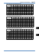
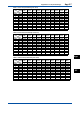
FLXA21 is programmed with the following table of conductivity of Potassium Chloride (KCl)
solutions at 25°C. This is used in the Automatic Cell Constant setting calibration feature. (See
chapter 9 on calibration) The table is derived from the Standards laid down in “International
RecommendationNo.56oftheOrganisationInternationaledeMétrologieLegale”.
Table 4 KCl values at 25 °C
Standard solution mol/l mg KCl/kg of solution Conductivity
1.000 M KCl 1.0 71135.2 111.31 mS/cm
0.100 M KCl 0.1 7419.13 12.852 mS/cm
0.010 M KCl 0.01 745.263 1.4083 mS/cm
0.005 M KCl 0.005 373.29 0.7182 mS/cm
0.002 M KCl 0.002 149.32 0.2916 mS/cm
0.001 M KCl 0.001 74.66 0.1469 mS/cm
Ifitismoreconvenient,theusermaymakesolutionsfromSodiumChloride(NaClorcommon
table salt) with the help of the following relationship table. This table is derived from the IEC norm
60746-3.
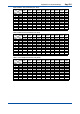
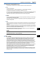
Table 5 NaCl values at 25 °C
Weight % mg/kg Conductivity
0.001 10 21.4 µS/cm
0.003 30 64.0 µS/cm
0.005 50 106 µS/cm
0.01 100 210 µS/cm
0.03 300 617 µS/cm
0.05 500 1.03 mS/cm
0.1 1000 1.99 mS/cm
0.3 3000 5.69 mS/cm
0.5 5000 9.48 mS/cm
1 10000 17.6 mS/cm
3 30000 48.6 mS/cm
5 50000 81.0 mS/cm
10 100000 140 mS/cm
For resistivity measurement the standard resistivity units of the calibration solution can be
calculated as follows:
R=1000/G(kΩ•cmifG=µS/cm)
Example:0.001%weight R=1000/21.4=46.7kΩ•cm
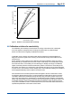
n MonitoringofPuriedWaterandWFIaccordingtoUSP<645>
FirstpublishedintheUSP23(TheUnitedStatesPharmacopeia,ed.23),theUSP<645>
describesaprocedureofmeasuringtheconductivityofPuriedWaterandWFI(Waterfor
Injection) instead of the previous complicated monitoring procedure. This procedure consists
ofthreestagesformeasuringtheconductivityofPuriedWaterandWFI.Onthestage1,
rstlythetemperatureofthewaterandthenon-temperature-compensatedconductivityofthe
water are measured, and this conductivity is compared with the limit conductivity value of the
correspondingtemperaturedirectedbyUSP<645>.(RefertoFigure3.)Iftheconductivityis
higher than the limit value, the procedure will proceed to the stage 2.
TheFLXA21hasthelimitvaluesofUSP<645>builtinthermware.Whentheerrorconguration
is set for this monitoring, the FLXA21 checks the non-temperature-compensated conductivity
with the limit value. If the conductivity is higher than the limit value, an error will be generated. A
safety margin to the limit value can be set on the FLXA21 to generate an error below limit value.
(Refer to the section 7.3.)
Whenthesafetymarginissetat20%,forexample,anerrorwillbegeneratedwhenthenon-
temperature-compensated conductivity goes higher than the 80% of the limit value at all
temperatures.Forexample,ifthetemperatureis64ºC.andthesafetymarginissetat20%,
thenanerrorwillbegeneratedat0.8x2.2μS/cm.=1.76μS/cm.(2.2μS/cmistheUSP<645>
limit value at 64ºC). In resistivity mode, an error will be generated at an non-temperature-
compensatedresistivityof0.568MΩ(=1/1.76μS/cm).
App.
SC