
User Manual


<15. OPERATION OF SENCOM pH/ORP>
15-8
IM 12A01A02-01E 5th Edition : Oct. 31, 2013-00
l Impedance 2
Impedanceshowstheelectricalresistanceofthereferenceelectrodeliquidjunction.Theliquid
junction forms the electrolytic contact between the reference electrode and the measuring
electrode,soitmustbekeptcleanandlledwithconductiveelectrolyte.Otherwisethe
measurement will suffer from instability, drift and measuring errors. The electrical impedance is
one of the most important.
In case of “Input Impedance setting” is “High” and the measured input-2 impedance value is
higherthan100kΩ,thedisplayshows“MΩRANGE”.Themeasuredinput-2impedancevalueis
lowerthan100kΩ,displayshows“BAD”.
If both impedance measurements are disabled (Error setting: Off), the display shows “- - - - (bar)”.
If either impedance measurement 1 or 2 is enabled, the display shows both the impedance
values.
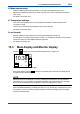
n Sensor wellness
At the Sensor wellness window, the soundness of a module is displayed. A larger number of n
in each gauge indicates that the parameter concerned is sound. A gauge is indicated for only
those parameters whose sensor wellness setting is “enabled,” while a bar (----) is displayed if the
sensor wellness setting is “disabled.”
SensorwellnesssetupcanbemadeinCommissioning→Measurementsetup→Sensordiag.
settings. For details, see section 16.2.7.
The “Reset wellness data” button can reset wellness data.
Whenasensororelectrodeisexchangedorreplaced,thewarning“SENCOMchanged”is
displayed depending on the settings (see Section 16.4). Reset the wellness data of the sensor.
NOTE
When a sensor is replaced, the replacement can be recorded manually into a logbook. (Refer to
thegure15.9.)
n Last calibrated
=dateonwhichthelastsensorcalibrationwasperformed.ThedisplayedvalueoftheZeroisthe
result of this calibration. The displayed value of Slope was calibrated on this date only if the last
calibration was a 2-point calibration.
n Calibration due
=thedatewhenthecalibrationmustbedonenextaccordingtothesettingsofthecalibration
interval.ThecalibrationintervalsaresetinCommissioning→Measurementsetup→Calibration
settings→Limitsandtiming.
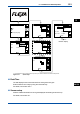
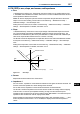
n Projected maintenance
The projected maintenance function predicts the date when the sensor unit will need recalibrating
for maintaining measurement accuracy. The function checks the input-2 impedance (reference
impedance) every 24 hours.
The function predicts the date when the input-2 impedance will cross the upper or lower limits,
and indicates the date and its status (the status is displayed in parentheses).
As shown in Figure 15.7, the date is predicted based on the intersection point of the upper or
lowerlimitsandtheextrapolatedlineofthevaluesobtainedbytheleastsquaresmethod.