
User Manual

<1. INTRODUCTION AND GENERAL DESCRIPTION>
1-5
IM 12A01A02-01E 5th Edition : Oct. 31, 2013-00
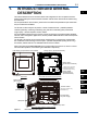
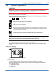
n Main display
10.38
Tag:FLXA21–PH
TEXT_PH1
TEXT_ORP1
TEXT_TEMP1
19
25.0
mV
4mA 20mAPH1
°C
pH
HOLD
WASH
Go to Home (Figure 1.6)
Go to Zoom (Figure 1.8)
Go to Infomation (Figure 1.10)
Go to Execute & Setup (Figure 1.11)
B
C
A
D
J
GEF
K H ML
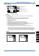
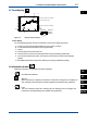
Figure 1.4 Example of main display
Main display
TheMaindisplayappearsuponstartupwhenonesensorisconnectedandtheMONITOR
display is disabled.
A: Measurement value: Primary value (large characters/user selectable)
B,C: Measurementvalue:Secondandtertiaryvalues(smallcharacters)
D:Unitfortheprimaryvalue
E: TagNo.(userprogrammable)
F: SensorNo.*
G:Sensorwellnessindicator(More■indicatethebettercondition.)
H: Hold/Wash indicators (appear only during the Hold/Wash operations)
J: Analog output display and parameter*(ex.:PH1…PH=Parameter,1=sensornumber)
K: Additionaltext(setinalphanumericcharacters/userprogrammable)
L: Functionbuttons(Home,Zoom,Status,Execute&Setup)
M: Fault/Warning indicators (indicated in blinking only during Fault/Warning status)
* Whentheparameterofwhichmeasurementvalueisindicatedisselectedasaprocess
parameter, that is, mA output set on the Output setup (refer to the section 5.3, 8.2, 11.2, and
14.3),itsSensorNo.isindicatedasawhitenumberintheblackbox,forexample
, and its
mA output is indicated as a bar at the bottom. At the bar, a parameter symbol is indicated.
NOTE
Measurement values on the display can be set independent of the process parameter.
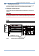
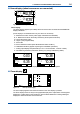
0.03
4mA 20mADiff-pH
pH
C
Sensor
2
Sensor
1
Calculated data
Differential
10.38
4mA 20mAPH1
pH
Sensor
2
Sensor
1
R
(
1
)
Redundant sys.
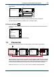
Figure 1.5 Example of calculated date and redundant system
1
PH
SC
ISC
DO
SENCOM