
User Manual


<13. COMMISSIONING OF DO (Dissolved Oxygen)>
13-5
IM 12A01A02-01E 5th Edition : Oct. 31, 2013-00
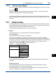
13.2.7 Sensor diag. settings
This screen is used to set items relating to sensor diagnostics displayed on the screens invoked
by pressing
.
Gauges are displayed for only parameters that have been enabled in “Sensor diag. settings.”
ParameterssettoDisableareprovidedwithabardisplay.
ThesettingparametersincludeProgresstimeandHeatcycle.Itisalsopossibletosetthe“Bad
limits” of the progress time and heat cycle and the “Heat cycle temp” and “Heat cycle time” of the
heat cycle.
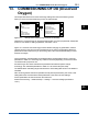
13.3 Output setup
Thegeneralprocedureistorstdenethefunctionoftheoutput,OutputorSimulate.Then,set
the process parameters associated with the output. On the Output, an output of measured value
is selected. On the Simulate, a simulation value can be set.
And,theparametersforHOLDfunctioncanbesetonthissetting.
l Output
Theoutputsignalisacurrentvaluespeciedbythefollowingparameters.
Process parameter
For the available process parameters, see Table 13.2.
The output of the selected process parameter is shown as a bar on the bottom of the Main
displayortheHomedisplay.Anditsparametersymbol(forexample,Oxygen1orDiff-Oxygen1)
is shown above the bar, too. When a selected process parameter is displayed as a measurement
value, the top left number or character is turned to be white number or character on black
background(forexample,
or ). (Refer to the section 1.2.)
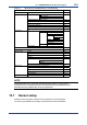
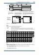
Table 13.2 List of Process Parameters
Number of sensors Process Parameters
1 Oxygen1(2)
Temperature1 (2)
2 Oxygen1
Temperature1
Oxygen2
Temperature2
Calculated*1
Redundant*2
*1: Refertosection13.8,Calculateddatasetup.
*2: Refertothe<Redundantsystem>below.
Calculated data and Redundant system are available when two modules are installed on the
instrument.
<Redundant system>
On the Redundant system, when a sensor (Sensor 1) of the 1st module fails, the output is
automatically switched to the output of the 2nd module.
After repairing the Sensor 1, manual reset of redundant system is necessary to return to the
output of 1st module from the output of the 2nd module.
DO
13